
The Hidden Cost of Mismatched Arduino Modules
Integrating third-party sensors, communication shields, and actuators into a microcontroller project is the core of the maker experience. However, as of 2026, the ecosystem has fractured into two distinct voltage domains: legacy 5V architectures (like the classic ATmega328P-based Uno and Nano) and modern 3.3V systems (dominated by the ESP32-S3, RP2040, and SAMD21). Plugging a 3.3V sensor into a 5V I/O pin, or overloading an onboard linear regulator, remains the leading cause of catastrophic silicon failure in DIY electronics.
This compatibility guide bypasses generic advice and dives into the exact electrical thresholds, logic translation matrices, and bus capacitance limits you need to verify before wiring any arduino modules to your development board.
The 5V vs 3.3V Logic Level Divide
Digital logic is not universally tolerant. A microcontroller's GPIO pin interprets voltage based on specific thresholds: VIH (minimum voltage guaranteed to be read as HIGH) and VIL (maximum voltage guaranteed to be read as LOW).
- 5V Logic (ATmega328P): Typically requires ~3.0V to register a HIGH. It safely accepts 3.3V inputs from modern modules without translation.
- 3.3V Logic (ESP32/RP2040): Max absolute rating on GPIO pins is usually 3.6V. Feeding a 5V signal from an older module into an ESP32 will forward-bias the internal ESD protection diodes, leading to immediate thermal destruction or latent latch-up failures.
For a comprehensive breakdown of semiconductor thresholds, refer to SparkFun's Logic Levels Tutorial, which details the exact CMOS and TTL voltage margins required for safe interoperability.
Real-World Module Failure Modes
Based on field returns and community troubleshooting, these are the most common compatibility traps when mixing arduino modules across voltage domains:
- NRF24L01+ PA+LNA Transceivers: The absolute maximum VCC for the nRF24L01+ silicon is 3.6V. Connecting the VCC pin to the 5V rail on an Arduino Uno will instantly vaporize the internal voltage regulator. Fix: Always use a dedicated 3.3V LDO or a logic-level translator board with onboard regulation.
- HC-SR04 Ultrasonic Sensors: These modules output a 5V pulse on the Echo pin. Connecting this directly to a Raspberry Pi Pico or ESP32 will degrade the 3.3V GPIO over time. Fix: Build a voltage divider using a 2kΩ and 3.3kΩ resistor to step the 5V Echo down to a safe ~3.11V.
- SIM800L GSM/GPRS Modules: While logically 3.3V tolerant, the SIM800L requires a strict 3.4V to 4.4V power supply and can draw 2A burst currents during RF transmission. Powering it from an Arduino's 3.3V or 5V pin will cause brownouts and network drops. Fix: Use a dedicated buck converter (like the LM2596) set to 4.0V.
Logic Level Translation Matrix
When bidirectional communication or high-speed SPI is required, resistor dividers are insufficient due to RC time constant delays. You must use active logic level shifters. Below is a comparison of the three most common translation ICs used in maker modules:
| Translator IC | Topology | Direction | Max Speed | Best Use Case | Typical Cost (2026) |
|---|---|---|---|---|---|
| BSS138 (MOSFET) | Open-Drain | Bidirectional | ~400 kHz | I2C buses, 1-Wire | $1.20 - $1.80 |
| CD4050B (Buffer) | CMOS Inverting/Non-Inverting | Unidirectional | ~5 MHz | SPI displays, SD cards | $0.80 - $1.50 |
| 74LVC245 | Transceiver | Bidirectional (Direction Pin) | ~100 MHz | High-speed parallel LCDs | $2.50 - $4.00 |
Expert Warning: Do not use BSS138 MOSFET-based shifters for SPI buses running above 1 MHz. The gate capacitance of the BSS138, combined with trace capacitance, will round off the square wave edges, causing SPI clock phase errors and silent data corruption on SD card modules.
I2C Bus Compatibility & Pull-Up Resistor Math
The I2C protocol uses open-drain outputs, meaning modules can only pull the SDA/SCL lines LOW; they rely on external pull-up resistors to bring the lines HIGH. A major compatibility issue arises when stacking multiple arduino modules on the same bus, as each breakout board often includes its own 4.7kΩ or 10kΩ pull-up resistors.
According to the NXP I2C-bus Specification (UM10204), the total bus capacitance (Cb) must not exceed 400 pF for standard mode (100 kHz) and fast mode (400 kHz). Furthermore, the pull-up resistor value must be calculated to ensure the rise time (tr) does not exceed 300 ns for fast mode.
Calculating Your Pull-Up Network
If you connect an OLED display (4.7kΩ pull-ups), a BME280 sensor (10kΩ pull-ups), and an MPU6050 (4.7kΩ pull-ups) to the same Arduino I2C bus, the resistors act in parallel:
1 / Rtotal = (1/4700) + (1/10000) + (1/4700)
Rtotal ≈ 1.85 kΩ
While 1.85 kΩ provides a very fast rise time, it forces the microcontroller's I/O pins to sink approximately (3.3V / 1850Ω) = 1.78 mA per line. This is within the 3 mA safe limit for an ESP32, but if you add a fourth module, you risk exceeding the GPIO current sink limit, resulting in a logic LOW that never quite reaches 0V, causing the Arduino Wire Library to hang indefinitely.
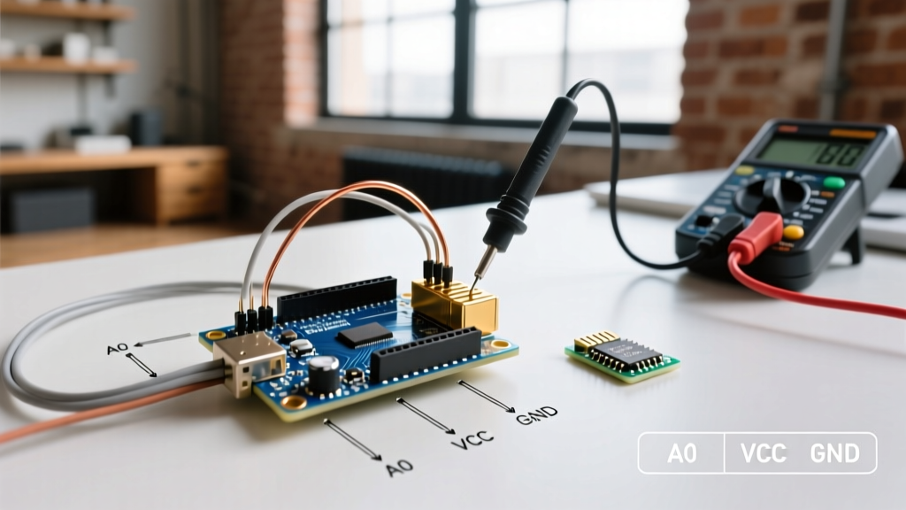
Actionable Fix: Use a multimeter to check the resistance between the SDA pin and VCC on every module before stacking them. If the parallel resistance drops below 2.0 kΩ, desurface-mount the pull-up resistors from the secondary modules using a hot air rework station, leaving only one master pull-up pair on the bus.
Power Delivery Realities: Linear vs. Switching Regulators
Compatibility is not just about logic levels; it is about current delivery. The classic Arduino Uno R3 utilizes an NCP1117-5.0 linear regulator. While rated for 1A on paper, thermal throttling severely limits its practical output.
- The Thermal Bottleneck: If you power the Uno via the barrel jack with a 12V adapter and draw 200mA for a servo module, the regulator must dissipate (12V - 5V) × 0.2A = 1.4W of heat. Without a heatsink, the NCP1117 will hit its 150°C thermal shutdown threshold in under 45 seconds.
- The 2026 Clone Alternative: Many modern third-party boards have replaced the linear regulator with a synchronous buck converter (like the MP2320). These switching regulators operate at 85%+ efficiency, allowing you to draw 500mA+ from the 5V pin without the board becoming hot to the touch. Always verify the regulator IC printed on your board's PCB before attaching high-draw modules like LED matrices or stepper drivers.
Step-by-Step Pre-Wiring Compatibility Audit
Before applying power to a new combination of arduino modules, execute this 5-point engineering audit:
- Verify Absolute Maximum VCC: Download the module's primary IC datasheet (not the seller's wiki). Check the Absolute Maximum Ratings table for VCC. If it says 3.6V, never connect to a 5V rail.
- Audit GPIO Tolerance: Check the microcontroller's datasheet for VIH and VIL. Ensure the module's output HIGH voltage exceeds the MCU's VIH threshold.
- Map the I2C Addresses: Use a hardware I2C scanner sketch to detect address conflicts. Modules like the PCA9685 PWM driver have jumper pads to shift addresses, while cheap LCD backpacks are often hardcoded to 0x27 or 0x3F.
- Calculate Peak Current Draw: Sum the peak mA ratings of all actuators and radios. If the total exceeds 400mA, bypass the onboard regulator and inject power directly into the 5V pin using an external buck converter.
- Check SPI Chip Select (CS) Lines: Ensure every SPI module has a dedicated CS pin routed to a unique GPIO. Sharing CS lines will cause bus contention and corrupted data registers.
Frequently Asked Questions
Can I power a 5V Arduino module using an ESP32's 5V pin?
Yes, but with a major caveat. The ESP32's "5V" pin is simply a passthrough from the USB VBUS. It is limited by the USB port's current limit (typically 500mA for USB 2.0) and the trace width on the dev board. It does not mean the ESP32's logic is 5V tolerant. You still need a level shifter for the data lines.
Why does my I2C OLED display work on an Uno but freeze on a Nano clone?
Cheap Nano clones often omit the 4.7kΩ pull-up resistors on the A4/A5 I2C pins to save manufacturing costs. The Uno R3 includes them. If your OLED module also lacks onboard pull-ups, the bus will float, causing the Wire library to hang. Soldering two 4.7kΩ resistors between VCC and SDA/SCL will resolve this instantly.
Are relay modules optically isolated?
Most standard 5V relay modules feature an optocoupler (like the PC817) for logic isolation, but they share a common ground between the logic side and the relay coil side to power the indicator LEDs. For true galvanic isolation required in high-voltage AC switching, you must remove the VCC-JDVCC jumper and supply the relay coil with a completely separate power source.