
The Internal ADC Bottleneck: Why You Need External Hardware
When designing precision sensor networks, the need to convert analog to digital Arduino signals accurately often pushes makers beyond the internal hardware limitations. The standard ATmega328P microcontroller (found in the Uno and Nano) features a 10-bit internal Analog-to-Digital Converter (ADC). At a 5V reference, this yields 1,024 discrete steps, equating to a resolution of roughly 4.88mV per step. While sufficient for basic potentiometer readings or crude battery voltage monitoring, this resolution is entirely inadequate for load cells, precision thermocouples, or audio signal sampling.
Furthermore, the internal ADC suffers from integral non-linearity (INL) and significant noise when reading high-impedance sources. To achieve true precision, you must bypass the internal ADC and interface an external chip. This compatibility guide breaks down the most reliable external ADC modules, their wiring requirements, and their compatibility across 5V and 3.3V Arduino ecosystems in 2026.
External ADC Compatibility Matrix
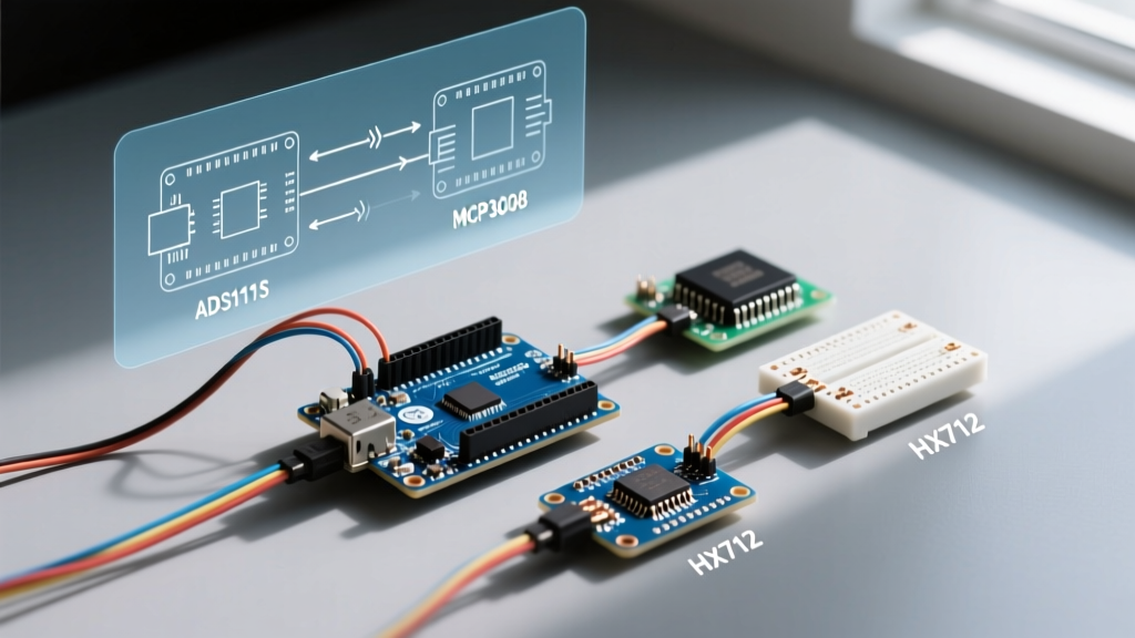
Choosing the right ADC depends on your target microcontroller's logic levels, required sampling rate, and resolution. Below is a compatibility and specification matrix for the most widely used external ADCs in the maker space.
| ADC Module / IC | Interface | Resolution | Max Sample Rate | Native Logic | Best Application | Avg. Cost (2026) |
|---|---|---|---|---|---|---|
| ADS1115 | I2C | 16-bit | 860 SPS | 2.0V - 5.5V | Precision sensors, pH meters, thermocouples | $4.50 - $6.00 |
| MCP3008 | SPI | 10-bit | 200 ksps | 2.7V - 5.5V | Audio sampling, multiplexed fast sensors | $2.50 - $3.50 |
| HX711 | Custom Serial | 24-bit | 80 SPS | 2.6V - 5.5V | Strain gauges, load cells, industrial scales | $1.20 - $2.00 |
| ADS1256 | SPI | 24-bit | 30 ksps | 5.0V | Seismology, high-end data acquisition | $12.00 - $18.00 |
I2C Precision: The ADS1115 Standard
The Texas Instruments ADS1115 is the undisputed king of general-purpose precision ADCs. It features four single-ended or two differential inputs, a Programmable Gain Amplifier (PGA), and an I2C interface. Because it operates from 2.0V to 5.5V, it is natively compatible with both 5V boards (Uno, Mega) and 3.3V boards (ESP32, Nano 33 IoT) without needing logic level shifters.
Wiring and I2C Configuration
- Address Selection: The ADDR pin dictates the I2C address. Tie it to GND for
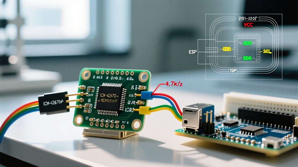
0x48, VDD for0x49, SDA for0x4A, or SCL for0x4B. This allows up to four modules on a single bus (16 total channels). - Pull-up Resistors: Most Adafruit and SparkFun breakouts include 10kΩ pull-up resistors on the SDA and SCL lines. If you are chaining multiple modules, the parallel resistance drops. For I2C buses running at 400kHz, you need a combined pull-up resistance of roughly 2.2kΩ to 4.7kΩ. If your bus capacitance exceeds 200pF (long wires), reduce pull-ups to 2.2kΩ or drop the bus speed to 100kHz.
- Decoupling: Always place a 100nF ceramic capacitor as close to the VCC and GND pins of the ADS1115 as possible to filter high-frequency switching noise from the microcontroller.
SPI Speed: The MCP3008 for Multiplexing
When you need to sample audio waveforms or read an array of analog joysticks rapidly, the 860 SPS limit of the ADS1115 becomes a bottleneck. The Microchip MCP3008 offers 8 channels of 10-bit resolution at up to 200 ksps (kilosamples per second) via SPI.
Compatibility Caveats with 3.3V Microcontrollers
While the MCP3008 can technically run on 3.3V, its maximum clock speed drops significantly at lower voltages (typically maxing out around 1.35 MHz at 3.3V compared to 3.6 MHz at 5V). If you are using an ESP32 or Arduino Due, you must configure your SPI clock divider accordingly in your sketch:
SPI.beginTransaction(SPISettings(1000000, MSBFIRST, SPI_MODE0));
Attempting to push a 10MHz SPI clock on a 3.3V MCP3008 will result in corrupted bitstreams and erratic analog readings. Furthermore, because SPI requires four separate wires (MOSI, MISO, SCK, CS) per chip, wiring multiple MCP3008s requires careful management of individual Chip Select (CS) pins to avoid bus contention.
24-Bit Load Cells: HX711 and ESP32 Edge Cases
The HX711 is a specialized 24-bit ADC designed exclusively for bridge sensors like load cells. It does not use standard I2C or SPI; instead, it uses a proprietary two-wire serial protocol (DOUT and SCK).
Expert Warning: ESP32 Watchdog Triggers
The standardHX711Arduino library relies on blockingdelayMicroseconds()or tightwhile()loops to clock the data out of the chip. On dual-core ESP32 boards running WiFi, these blocking loops can starve the FreeRTOS idle task, triggering the Task Watchdog Timer (TWDT) and resetting your board. Always use an interrupt-driven HX711 library (such asHX711_MPor hardware timer callbacks) when integrating load cells with WiFi-enabled MCUs.
Voltage Translation: Bridging 5V and 3.3V Worlds
A common failure mode when upgrading to modern MCUs like the ESP32-S3 or Arduino Portenta is frying 3.3V peripherals with 5V logic. While the ADS1115 is tolerant of both, chips like the ADS1256 are strictly 5V. If you must interface a 5V ADC with a 3.3V Arduino, you must use a logic level converter.
Do not rely on simple resistor voltage dividers for high-speed SPI or I2C lines; the parasitic capacitance of the resistors will round off the square waves, causing communication failures at high baud rates. Instead, use a bi-directional logic level shifter based on the BSS138 N-channel MOSFET. These breakout boards cost roughly $1.50 to $3.00 and safely translate I2C and SPI signals without degrading edge transition times.
For a deeper understanding of why CMOS logic thresholds matter in mixed-voltage environments, refer to the SparkFun Tutorial on Logic Levels, which details the exact V_IH and V_IL thresholds for standard 74HC and 4000-series logic families often used in DIY ADC multiplexing.
Troubleshooting Common ADC Failure Modes
Even with the right hardware, analog-to-digital conversion is highly susceptible to environmental noise. If your external ADC is returning jittery or locked values, check these specific failure modes:
- Floating Inputs: An unconnected ADC pin acts as an antenna. If you are only using two of the four channels on an ADS1115, tie the unused analog inputs directly to AGND. Leaving them floating will inject capacitive crosstalk into your active channels.
- Ground Loops: If your sensor is powered by a separate switching power supply (e.g., a 12V buck converter powering a pressure transducer), the ground potential between the sensor and the Arduino may differ by tens of millivolts. This destroys 16-bit and 24-bit readings. Use a star grounding topology where the sensor ground, ADC ground, and microcontroller ground all meet at a single physical point.
- Source Impedance Mismatch: The MCP3008 internal sampling capacitor requires a low-impedance source to charge fully within the acquisition window. If you are reading a high-impedance voltage divider (e.g., >10kΩ resistors), the reading will drift based on the sampling rate. Buffer the signal with an op-amp (like the MCP6001) or place a 100nF capacitor directly at the ADC input pin to act as a local charge reservoir.
Summary
Knowing how to properly convert analog to digital Arduino signals requires matching the ADC architecture to your specific physical constraints. Use the ADS1115 for high-resolution, low-speed I2C sensor polling. Deploy the MCP3008 when you need multi-channel SPI speed for audio or fast transient capture. Rely on the HX711 strictly for 24-bit strain gauge applications, ensuring you handle RTOS timing correctly on modern WiFi MCUs. Always respect logic level thresholds and prioritize star-grounding to preserve the integrity of your digital conversions.