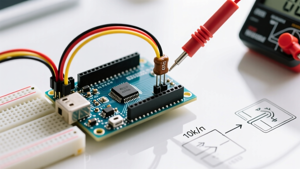

Why Your Transistor with Arduino Keeps Failing
Integrating a transistor with Arduino microcontrollers is a fundamental rite of passage for electronics makers. Whether you are driving a 12V DC motor, switching a high-power LED strip, or triggering a mechanical relay, the Arduino's ATmega328P I/O pins simply cannot handle the current. According to the Arduino Digital Pins Documentation, these pins are limited to an absolute maximum of 40mA per pin (with a recommended continuous limit of 20mA). Bridging the gap between low-voltage logic and high-current loads introduces severe failure points. If you are experiencing overheated components, random triggering, or dead I/O pins, you are likely falling victim to one of five critical diagnostic errors. Let us break down the exact failure modes and how to troubleshoot them on your workbench.
Error 1: The 'Magic Smoke' Failure (Missing Base Resistor)
The Symptom: The Arduino pin gets hot, the transistor overheats instantly, or the microcontroller resets/fails permanently.
The Diagnosis: You connected an Arduino I/O pin directly to the base of a Bipolar Junction Transistor (BJT) like the 2N2222A or 2N3904 without a current-limiting resistor. The base-emitter junction of a BJT acts exactly like a standard silicon diode, with a forward voltage drop of approximately 0.7V. If you apply 5V directly from the Arduino, the transistor will attempt to draw as much current as the power source can supply, far exceeding the 40mA absolute maximum rating of the ATmega328P.
The Fix: Apply Ohm's Law to calculate the correct base resistor. If you want to limit the base current to a safe 20mA:
- Formula: R = (V_pin - V_be) / I_base
- Calculation: R = (5V - 0.7V) / 0.020A = 215 Ohms
Use a standard 220 Ohm or 1k Ohm resistor in series with the base pin. As detailed in the ON Semiconductor P2N2222A Datasheet, a 1k Ohm resistor will provide roughly 4.3mA of base current, which is sufficient to saturate the transistor for loads up to 400mA (assuming a conservative hFE gain of 100).
Error 2: The 'Weak Switch' Trap (Standard vs. Logic-Level MOSFETs)
The Symptom: The load turns on partially, the MOSFET becomes too hot to touch, and there is a massive voltage drop across the load.
The Diagnosis: You used a standard power MOSFET (like the infamous IRF520) instead of a logic-level MOSFET. Many beginners look at the Gate Threshold Voltage (Vgs(th)) on a datasheet, see that it is rated at 2.0V to 4.0V, and assume a 5V Arduino pin will turn it fully on. This is a catastrophic misunderstanding of semiconductor physics. Vgs(th) is merely the voltage at which the MOSFET barely begins to conduct (usually at a mere 250 microamps). To achieve the low Rds(on) (Drain-Source On-Resistance) required to switch high currents without thermal runaway, standard MOSFETs require 10V to 12V at the gate.
| Component Type | Example Part | Drive Voltage (Vgs/Vbe) | Arduino 5V Compatibility | Typical Cost (2026) |
|---|---|---|---|---|
| Standard NPN BJT | 2N2222A | 0.7V (Base-Emitter) | Excellent (Requires Base Resistor) | $0.15 |
| Darlington BJT | TIP120 | 1.25V (Base-Emitter) | Good (High Vce saturation drop) | $0.85 |
| Standard MOSFET | IRF520 | 10V (Fully Enhanced) | Poor (Will overheat at 5V logic) | $0.90 |
| Logic-Level MOSFET | IRLZ44N | 5V (Fully Enhanced) | Excellent (Low Rds(on) at 5V) | $1.60 |
The Fix: Always select MOSFETs with an 'L' in the prefix (e.g., IRLZ44N, IRLB8721) or verify in the datasheet that the Rds(on) is explicitly specified at Vgs = 4.5V or 5.0V. For a broader overview of semiconductor switching characteristics, the SparkFun Transistor Tutorial provides excellent visual breakdowns of these operational regions.
Error 3: The 'Ghost Trigger' (Floating Gates and Bases)
The Symptom: The load turns on randomly when the Arduino boots up, or triggers when the pin is configured as an INPUT or temporarily disconnected.
The Diagnosis: MOSFET gates have incredibly high impedance, meaning they act like tiny capacitors. Stray electromagnetic interference (EMI) from nearby wires, or the floating state of an Arduino pin during the bootloader sequence, can capacitively couple enough charge onto the gate to accidentally exceed the threshold voltage. BJTs can also suffer from leakage currents causing partial turn-on.
The Fix: You must install a 10k Ohm pull-down resistor between the Base/Gate and the common Ground. This provides a safe discharge path for stray capacitance and ensures the transistor remains firmly in the 'OFF' state until the Arduino actively drives the pin HIGH.
Error 4: The 'Back-EMF Spike' (Missing Flyback Diode)
The Symptom: The Arduino resets randomly exactly when the motor, relay, or solenoid turns OFF. In severe cases, the transistor fails into a permanent short-circuit.
The Diagnosis: Inductive loads store energy in their magnetic fields. When the transistor switches off, the magnetic field collapses, inducing a massive reverse voltage spike (calculated by V = -L * di/dt). This inductive kickback can easily generate 50V to 100V spikes, instantly punching through the 60V or 100V breakdown voltage of your transistor and destroying the silicon junction.
The Fix: Wire a 1N4007 rectifier diode in parallel with the inductive load, with the cathode (striped end) pointing toward the positive voltage supply and the anode pointing toward the transistor's Drain/Collector. This 'flyback' or 'freewheeling' diode clamps the voltage spike to a safe ~0.7V above the supply rail.
Error 5: The 'Common Ground' Omission
The Symptom: The circuit is wired perfectly, the code is correct, but absolutely nothing happens. No current flows.
The Diagnosis: Voltage is a relative measurement. The 5V signal coming from the Arduino's digital pin is referenced to the Arduino's GND. If your external 12V power supply's GND is not connected to the Arduino's GND, the transistor has no reference point to understand what '5V' means. The circuit is effectively an open loop.
The Fix: Always run a dedicated jumper wire connecting the GND pin of the Arduino to the negative terminal (GND) of your external power supply. Use a multimeter in continuity mode to verify this connection before applying power.
2026 Maker Pro-Tip: When diagnosing a failing transistor circuit, use your multimeter to measure the voltage drop across the transistor's Collector-Emitter (BJT) or Drain-Source (MOSFET) while under load. A properly saturated BJT should show less than 0.3V. A fully enhanced logic-level MOSFET should show less than 0.1V. If you measure 2V or higher, your transistor is operating in its linear (resistive) region and is burning up excess power as heat.
Frequently Asked Questions (FAQ)
Can I use a TIP120 Darlington transistor for PWM motor control?
While the TIP120 is popular in legacy kits, it is a Darlington pair, meaning it has a high Collector-Emitter saturation voltage (Vce(sat)) of up to 2.0V at 3A. If you are switching 3A through a TIP120, it will dissipate 6 Watts of heat (P = 3A * 2.0V), requiring a massive heatsink. For PWM motor control in 2026, a logic-level MOSFET like the IRLB8721 is vastly superior, dissipating less than 0.1W under the same conditions due to its milliohm-level Rds(on).
Why does my logic-level MOSFET get hot when switching 10A, even with a 5V gate drive?
Check your gate drive circuit. If you are using PWM at high frequencies (e.g., 20kHz), the Arduino's 40mA pin cannot charge and discharge the MOSFET's gate capacitance fast enough. The MOSFET spends too much time transitioning through the linear region. To fix this, use a dedicated MOSFET gate driver IC (like the TC4420) or a simple push-pull BJT totem-pole circuit to provide the 1A+ peak current needed to switch the gate instantly.
Diagnostic Checklist Summary
- Verify Base/Gate Resistor: 220 Ohm to 1k Ohm for BJTs; 100 Ohm to 220 Ohm for MOSFET gates.
- Confirm Pull-Down: 10k Ohm resistor from Gate/Base to GND.
- Check MOSFET Datasheet: Ensure Rds(on) is rated at Vgs = 4.5V or 5V.
- Install Flyback Diode: 1N4007 across relays, motors, and solenoids.
- Tie Grounds Together: Arduino GND must share a common node with external PSU GND.