
Engineering an Automated Arduino Mist Maker System
Building a reliable Arduino mist maker requires more than simply connecting an ultrasonic transducer to a digital pin. Whether you are automating a closed-loop terrarium, a greenhouse propagation chamber, or a reptile enclosure, the core challenge lies in managing high-current 24V DC loads safely while protecting the microcontroller from inductive kickback and thermal degradation. This configuration guide details the exact hardware topology, logic-level MOSFET selection, and non-blocking C++ code required to deploy a robust ultrasonic atomization system in 2026.
Piezoelectric Physics & Frequency Selection
Ultrasonic mist makers operate via a piezoelectric ceramic ring that vibrates at high frequencies to create capillary waves on the water's surface. When the wave amplitude exceeds a critical threshold, micro-droplets are ejected as a fine fog. For most maker applications, you will encounter two primary frequencies:
- 1.7 MHz (Standard): Produces a heavier, denser mist with larger droplet sizes (10-25 microns). Ideal for terrariums and greenhouse humidity where droplets need to travel a short distance without evaporating instantly.
- 2.4 MHz to 3.0 MHz (Fine): Produces a much finer aerosol (1-5 microns). Best suited for inhalation therapy devices or rapid-humidity enclosures where immediate evaporation is desired.
This guide focuses on the widely available 24V DC 1.7MHz atomizer modules, which typically draw between 800mA and 1.5A under load. Because the Arduino Uno or Nano operates at 5V logic and can only source ~20mA per I/O pin, an intermediary switching component is mandatory.
Hardware Bill of Materials (2026 Pricing)
Selecting the correct switching component is the most common point of failure in DIY fogger circuits. Many beginners mistakenly use a BJT Darlington transistor like the TIP120 or a standard IRF520 MOSFET. The TIP120 suffers from a high voltage drop (~2V) resulting in massive heat dissipation at 1.5A. The IRF520 requires 10V at the gate to fully open, meaning a 5V Arduino pin will leave it in the linear (high-resistance) region, causing thermal runaway.
| Component | Specification / Model | Est. Price (2026) | Purpose |
|---|---|---|---|
| Ultrasonic Module | 24V DC 1.7MHz Atomizer w/ 20mm Piezo | $14.00 | Mist generation |
| Power Supply | Mean Well GST60A24 (24V 2.5A) | $22.50 | Stable high-current DC |
| Switching MOSFET | IRLZ44N (Logic-Level N-Channel) | $1.80 | 5V logic to 24V load switching |
| Flyback Diode | 1N4007 Rectifier | $0.10 | Inductive spike protection |
| Water Level Sensor | Stainless Steel Magnetic Float Switch | $5.50 | Dry-run prevention |
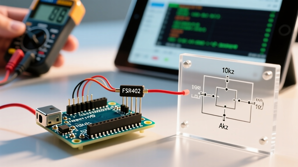
| Gate Pull-down | 10kΩ Carbon Film Resistor | $0.05 | Prevents floating gate on boot |
Circuit Configuration & Wiring Topology
Proper wiring ensures the longevity of both your Arduino and the piezoelectric transducer. Follow this exact topology to configure the circuit.
1. The MOSFET Switching Stage
The IRLZ44N is a logic-level MOSFET with a Gate-Source Threshold Voltage (Vgs(th)) of 1V to 2V, and an On-Resistance (Rds(on)) of just 22mΩ when driven at 5V. According to the SparkFun Transistor Guide, ensuring the MOSFET is fully saturated prevents it from acting as a resistor and generating excess heat.
- Connect the Arduino Digital Pin 9 to the Gate of the IRLZ44N via a 220Ω current-limiting resistor.
- Connect a 10kΩ pull-down resistor between the Gate and Source (Ground). This is critical: during Arduino boot-up, I/O pins float. Without this resistor, the MOSFET may rapidly oscillate, destroying the component and the piezo driver board.
- Connect the Source pin to the common Ground (Arduino GND and 24V PSU V-).
2. Load & Flyback Protection
Although the piezo element is primarily capacitive, the onboard driver circuitry of commercial 24V mist makers contains inductors. When the MOSFET switches off, the collapsing magnetic field generates a high-voltage reverse spike.
- Connect the 24V PSU V+ to the Positive terminal of the mist maker.
- Connect the Negative terminal of the mist maker to the Drain of the IRLZ44N.
- Solder a 1N4007 flyback diode in reverse bias across the mist maker terminals (Cathode/Stripe to V+, Anode to Drain). This clamps the voltage spike, protecting the MOSFET's internal junction.
3. Dry-Run Protection Integration
Running an ultrasonic atomizer without water causes the piezo ceramic to overheat and shatter within seconds. Wire a magnetic float switch between Arduino Digital Pin 2 and Ground. Enable the internal pull-up resistor in your code to detect when the water level drops below the sensor threshold.
Arduino Code: Non-Blocking Duty Cycle Control
Continuous operation of a 1.7MHz mist maker will overheat the water and degrade the piezo ring. Professional agricultural controllers use a duty cycle (e.g., 15 minutes ON, 45 minutes OFF). We utilize the millis() function to achieve this without blocking the microcontroller, allowing you to add temperature or humidity sensors later. For more on non-blocking timing, refer to the Arduino PWM and Timing Documentation.
// Arduino Mist Maker Configuration Code
const int MIST_PIN = 9;
const int WATER_SENSOR_PIN = 2;

// Timing variables (in milliseconds)
const unsigned long ON_DURATION = 900000;   // 15 Minutes
const unsigned long OFF_DURATION = 2700000; // 45 Minutes

unsigned long previousMillis = 0;
bool isMisting = false;

void setup() {
  pinMode(MIST_PIN, OUTPUT);
  pinMode(WATER_SENSOR_PIN, INPUT_PULLUP); // Active LOW when water is present
  digitalWrite(MIST_PIN, LOW); // Ensure OFF on boot
  Serial.begin(9600);
}

void loop() {
  unsigned long currentMillis = millis();
  bool waterPresent = (digitalRead(WATER_SENSOR_PIN) == LOW);

  // Safety Override: Kill mist immediately if water is low
  if (!waterPresent) {
    digitalWrite(MIST_PIN, LOW);
    isMisting = false;
    previousMillis = currentMillis; // Reset timer to prevent immediate restart when refilled
    return;
  }

  // Duty Cycle Logic
  if (isMisting && (currentMillis - previousMillis >= ON_DURATION)) {
    digitalWrite(MIST_PIN, LOW);
    isMisting = false;
    previousMillis = currentMillis;
    Serial.println("Cycle: Mist OFF (Resting)");
  }
  else if (!isMisting && (currentMillis - previousMillis >= OFF_DURATION)) {
    digitalWrite(MIST_PIN, HIGH);
    isMisting = true;
    previousMillis = currentMillis;
    Serial.println("Cycle: Mist ON (Active)");
  }
}
Operational Edge Cases & Troubleshooting
Even with a perfect schematic, environmental factors in high-humidity enclosures can introduce edge cases. Here is how to diagnose and resolve the most common field issues:
Safety Warning: Never operate the 24V ultrasonic module in air for more than 3 seconds. The piezoelectric ceramic relies on the thermal mass of the water to dissipate heat generated by internal friction. Dry firing will cause catastrophic depolarization and physical cracking.
Edge Case 1: Weak or Asymmetrical Mist Output
Cause: Mineral scaling (calcium carbonate) on the piezoelectric membrane. As tap water evaporates, minerals concentrate and coat the transducer, dampening the 1.7MHz vibration.
Solution: Use distilled or reverse-osmosis (RO) water. If scaling has already occurred, remove the module and soak the ceramic ring in a 5% white vinegar solution for 15 minutes. Never scrape the ceramic surface with metal tools, as micro-scratches will create stress concentration points that lead to shattering.
Edge Case 2: Arduino Randomly Resetting or Brownouts
Cause: Inrush current or inductive kickback coupling back into the 5V rail. When the MOSFET switches a highly reactive load, ground bounce can occur if the high-current 24V ground path shares a thin wire with the Arduino logic ground.
Solution: Implement a star-ground topology. Run a dedicated, thick-gauge (18 AWG) ground wire from the 24V PSU directly to the MOSFET Source, and a separate ground wire from the PSU to the Arduino GND pin. Additionally, place a 100µF electrolytic capacitor across the 24V input terminals of the mist maker to buffer inrush current demands.
Edge Case 3: Condensation Shorting the Logic Board
Cause: In enclosed terrariums, ambient humidity easily exceeds 90%, leading to condensation on the Arduino PCB, which causes leakage currents across I/O pins and eventual corrosion.
Solution: Mount the Arduino and MOSFET circuitry in an IP65-rated project enclosure outside the humid zone. Pass only the sealed 24V wires and the float switch wires through a waterproof cable gland into the terrarium. Conformal coating (e.g., MG Chemicals 419D) on the Arduino PCB provides a secondary layer of defense against sulfur and moisture ingress.
Summary of Best Practices
Configuring an Arduino mist maker successfully hinges on respecting the electrical characteristics of both the piezoelectric load and the microcontroller. By utilizing a logic-level IRLZ44N MOSFET, enforcing strict dry-run protections via a magnetic float switch, and managing thermal loads through a non-blocking software duty cycle, you ensure a maintenance-free, highly reliable humidity control system. For further reading on protecting microcontrollers from inductive loads, the Adafruit Guide to Transistors and MOSFETs provides excellent foundational theory on flyback diode placement and gate drive requirements.