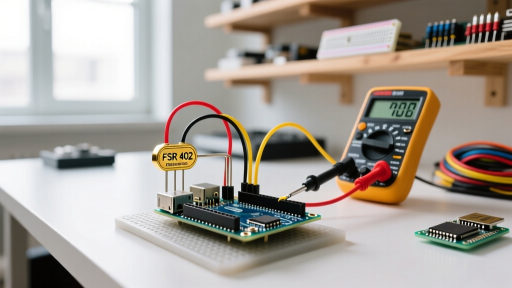

The Anatomy of a Force Sensitive Resistor (FSR)
A Force Sensitive Resistor (FSR) is a piezoresistive sensor that decreases in electrical resistance as the applied mechanical force increases. Unlike strain gauges that rely on the deformation of a metallic foil, FSRs utilize a polymer thick film (PTF) matrix. When pressure is applied to the active sensing area, the conductive particles within the polymer are forced closer together, creating more percolation pathways for electrons and thereby lowering the overall resistance.
For Arduino makers and embedded engineers, FSRs are highly attractive due to their ultra-thin profile (often less than 0.3mm), flexibility, and low cost. However, they are fundamentally qualitative sensors rather than high-precision metrology instruments. Understanding their non-linear response curve and physical limitations is the difference between a successful interactive art installation and a frustrating debugging session.
Choosing the Right FSR: FSR 402 vs. FlexiForce A201
Not all force-sensitive resistors are created equal. The market is dominated by two primary tiers: consumer-grade hobbyist sensors (like the Interlink Electronics FSR series) and industrial-grade sensors (like the Tekscan FlexiForce line). Below is a 2026 market comparison of the most common models used in microcontroller projects.
| Specification | Interlink FSR 402 | Tekscan FlexiForce A201 |
|---|---|---|
| Active Sensing Area | 18mm diameter (0.71 in) | 9.53mm diameter (0.375 in) |
| Force Range | 0.2 N to 20 N | 0.2 N to 25 N (Standard) |
| Resistance at Rest | > 1 MΩ | > 5 MΩ |
| Repeatability | ± 2.5% | ± 2.5% |
| Linearity | Poor (Logarithmic) | Moderate (± 5%) |
| Typical Price (2026) | $9.95 USD | $16.50 USD |
For most hobbyist Arduino projects, the Interlink FSR 402 is the standard choice. However, if you are building a medical device, a robotic gripper requiring precise pinch-force feedback, or an industrial scale, the Tekscan FlexiForce A201 offers vastly superior consistency and lower hysteresis.
The Voltage Divider: Interfacing FSR to Arduino ADC
Microcontrollers like the ATmega328P (Arduino Uno) or the ESP32 cannot measure resistance directly; they measure voltage. To convert the FSR's variable resistance into a readable voltage, we must use a voltage divider circuit.
The formula for the output voltage ($V_{out}$) read by the Arduino's Analog-to-Digital Converter (ADC) is:
V_{out} = V_{cc} * (R_{ref} / (R_{fsr} + R_{ref}))
Selecting the Optimal Reference Resistor ($R_{ref}$)
The choice of your pull-down resistor ($R_{ref}$) dictates the sensitivity range of your sensor. If $R_{ref}$ is too high, you lose resolution at high forces. If it is too low, you lose resolution at light touches.
- Light Touch Applications (0.2N - 5N): FSR resistance ranges from ~100kΩ down to ~15kΩ. Use a 33kΩ reference resistor.
- General Purpose (0.2N - 20N): FSR resistance ranges from ~100kΩ down to ~1kΩ. Use a 10kΩ reference resistor.
- Heavy Squeeze Applications (5N - 100N): FSR resistance ranges from ~15kΩ down to ~250Ω. Use a 3.3kΩ reference resistor.
For a comprehensive breakdown of Arduino analog pin behavior and ADC sampling rates, refer to the official Arduino Analog Read Documentation.
Step-by-Step Wiring and Circuit Protection
One of the most common failure modes in FSR integration is mechanical damage to the sensor's tail. The silver traces are printed on a fragile polymer substrate.
CRITICAL WARNING: Never solder directly to the exposed pins of a standard FSR with a standard 350°C soldering iron. The heat will melt the polymer substrate, delaminating the traces and permanently destroying the sensor. Instead, use conductive epoxy, specialized zero-insertion-force (ZIF) connectors, or purchase FSRs pre-terminated with JST connectors.
Wiring the Circuit:
- Connect one leg of the FSR to the Arduino 5V (or 3.3V for ESP32) pin.
- Connect the other leg of the FSR to an analog input pin (e.g., A0).
- Connect one leg of your chosen $R_{ref}$ (e.g., 10kΩ) to A0 (the junction point).
- Connect the other leg of the $R_{ref}$ to GND.
- Optional but recommended: Add a 0.1µF ceramic capacitor between A0 and GND to filter out high-frequency EMI noise, which is especially prevalent when using switching power supplies.
Arduino Code: Linearizing the Non-Linear Response
Because the resistance of an FSR drops logarithmically as force increases, mapping the raw ADC value directly to force will yield terrible results. The secret to FSR programming is to convert the resistance into Conductance ($G = 1/R$). Conductance has a remarkably linear relationship with applied force.
// FSR Linearization Code for Arduino Uno (10-bit ADC)
const int fsrPin = A0;
const float Vcc = 5.0;
const float R_ref = 10000.0; // 10k Ohm reference resistor

void setup() {
  Serial.begin(115200);
  analogReference(DEFAULT);
}

void loop() {
  int adcRaw = analogRead(fsrPin);

  // Prevent division by zero when no force is applied
  if (adcRaw < 5) {
    Serial.println("Force: 0.00 N");
    delay(100);
    return;
  }

  // 1. Convert ADC to Voltage
  float voltage = (adcRaw * Vcc) / 1023.0;

  // 2. Calculate FSR Resistance
  float R_fsr = R_ref * ((Vcc / voltage) - 1.0);

  // 3. Calculate Conductance (1/R)
  float conductance = 1.0 / R_fsr;

  // 4. Map Conductance to Force (Newtons)
  // Note: The multiplier below (approx 11375) is derived from
  // the FSR 402 datasheet conductance vs. force slope.
  float forceNewtons = conductance * 11375.0;

  Serial.print("Raw: "); Serial.print(adcRaw);
  Serial.print(" | Resistance: "); Serial.print(R_fsr); Serial.print(" ohms");
  Serial.print(" | Force: "); Serial.print(forceNewtons); Serial.println(" N");

  delay(100);
}
For a deeper dive into physical circuit integration and mechanical mounting best practices, the SparkFun FSR Hookup Guide remains an industry-standard reference for makers.
Real-World Edge Cases: Why Your FSR Readings Drift
If you leave an object resting on an FSR and watch the Serial Monitor, you will notice the reported force slowly dropping over time. This is not a code bug; it is a physical property of the polymer matrix. To design robust systems, you must account for these three edge cases:
1. Creep (Logarithmic Drift)
Under a constant static load, the polymer in the FSR continues to compress microscopically over time. This causes the resistance to slowly drop, making the Arduino think the force is increasing. If your application requires holding a static weight measurement for more than 5 seconds, you must implement a software high-pass filter or use a capacitive load cell instead.
2. Hysteresis
FSRs exhibit hysteresis, meaning the resistance value during the loading phase (pressing down) is different from the unloading phase (releasing). Standard FSR 402 sensors can have a hysteresis error of up to 15%. To mitigate this, always calibrate your system in the direction of force application (e.g., if measuring a footstep, calibrate by stepping on the sensor, not by pressing it with your hand and releasing).
3. Shear Force Destruction
FSRs are designed exclusively for normal forces (perpendicular to the sensor surface). Applying lateral or shear forces (sliding an object across the sensor) will scrape the conductive polymer off the substrate, causing permanent dead zones. Always mount the FSR between two flat, rigid surfaces with a thin layer of high-density foam to distribute the load evenly and prevent localized shear.
Upgrading Precision: Bypassing the 10-Bit Internal ADC
The standard Arduino Uno features a 10-bit ADC, yielding 1,024 discrete steps across the 0-5V range. When measuring light touches where the voltage change is minimal, 10 bits is often insufficient, resulting in "stair-step" jitter in your force data.
The Solution: Integrate an external ADS1115 16-bit ADC module via I2C. The ADS1115 provides 32,768 steps of resolution and features a built-in Programmable Gain Amplifier (PGA). By setting the PGA to ±2.048V, you can achieve micro-Newton level resolution changes in your FSR readings. This upgrade costs roughly $4.50 USD and is mandatory for any FSR project intended for musical MIDI controllers or medical rehabilitation grip-strength trackers.
Summary
Interfacing a force sensitive resistor with an Arduino requires more than just an analogRead() command. By selecting the correct pull-down resistor for your target force range, protecting the fragile sensor tabs from heat and shear forces, and linearizing the data via conductance math, you can extract highly reliable, actionable force data for your embedded systems.