
The Anatomy of an Unresponsive Input
There are few things more frustrating in embedded systems than uploading a flawless sketch, pressing your input switch, and watching the serial monitor do absolutely nothing. It is incredibly common to frantically search for an 'arduino buton' fix when your circuit suddenly stops responding, but the root cause is rarely a defective microcontroller. In 95% of cases, the failure lies at the intersection of mechanical switch physics, breadboard parasitics, and improper pin configuration.
As of 2026, the maker market is flooded with ultra-cheap tactile switches and clone boards. While a 100-pack of generic 6x6mm tactile switches might only cost around $3.50 online, their quality control is notoriously inconsistent. Contact oxidation, weak internal phosphor bronze springs, and improper solder bath flux residue can all lead to intermittent connections. This guide provides a systematic, engineer-level approach to diagnosing and fixing unresponsive Arduino button circuits, moving from the physical layer up to software logic traps.
Phase 1: Hardware Diagnostics and the Physical Layer
Before touching your IDE, you must verify the physical integrity of the circuit. Generic tactile switches, such as the widely cloned versions of the Omron B3F series, are rated for a contact resistance of less than 100mΩ and an insulation resistance of 100MΩ. However, cheap clones often exhibit severe contact degradation after just a few hundred actuations.
The Multimeter Continuity Test
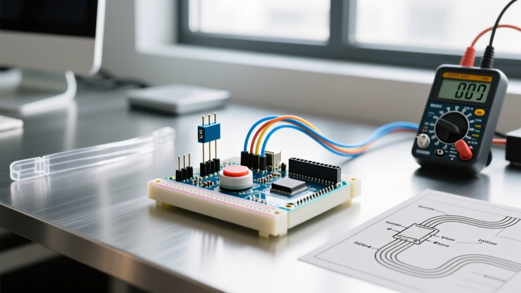
Set your digital multimeter (DMM) to the continuity or 200Ω resistance range. Place the probes on the diagonal pins of the tactile switch (pins 1 and 4, or 2 and 3, depending on the internal bridge orientation).
- Unpressed State: The meter should read 'OL' (Open Loop) or infinite resistance.
- Pressed State: The meter should read between 0.1Ω and 2.0Ω. If you see resistance fluctuating wildly above 10Ω while holding the button down, the internal contacts are oxidized or pitted. Replace the switch immediately.
Breadboard Wear and Parasitic Faults
Solderless breadboards are notorious for hidden failures. The internal metal clips lose their spring tension over time. If you have inserted and removed jumper wires into the same row more than 50 times, the contact resistance can spike to 50Ω or higher, causing voltage drops that the Arduino's digital input buffer interprets as a floating state. Fix: Move your button circuit to a fresh set of breadboard rails, or better yet, solder the switch and pull-up resistor to a 0.1-inch perfboard for permanent deployments.
Phase 2: The Pull-Up/Pull-Down Paradigm
A floating pin is the most common reason an Arduino button appears 'broken.' Microcontroller GPIO pins are high-impedance inputs. If a pin is connected to a button that is currently open (unpressed), the pin is essentially acting as an antenna, picking up electromagnetic interference (EMI) from nearby wires, switching power supplies, and even your body's capacitance.
Internal vs. External Resistors
Historically, makers wired a 10kΩ external resistor to 5V (pull-up) or GND (pull-down). Today, leveraging the microcontroller's internal pull-up resistors is the standard best practice. According to the official Arduino INPUT_PULLUP documentation, the internal pull-up resistors on ATmega328P and ESP32 chips typically range between 20kΩ and 50kΩ.
Pro-Tip for 2026 ESP32 Users: If you are using an ESP32-S3 or C3, be aware that GPIO 0 through GPIO 5 have specific strapping pin behaviors during boot. Wiring a button with an external pull-down to GPIO 0 can force the ESP32 into flash download mode on startup, making it seem like your button code is failing to run. Always useINPUT_PULLUP and wire the button to GND on these specific pins.
Phase 3: Signal Integrity and Switch Bounce
Mechanical switches do not transition cleanly from OPEN to CLOSED. When the metal contacts collide, they physically bounce apart and back together multiple times before settling. This phenomenon, known as contact bounce, typically lasts between 5ms and 20ms. To an Arduino running at 16MHz, a single button press looks like dozens of rapid HIGH/LOW transitions.
Hardware Debouncing (The RC Filter)
For mission-critical hardware where software latency is unacceptable, you can debounce the signal in analog. By placing a 10kΩ resistor in series with the switch and a 0.1μF ceramic capacitor in parallel with the GPIO pin to GND, you create a low-pass RC filter. The time constant (τ = R × C) is 1ms, which smoothly charges and discharges, effectively masking the microsecond-level bounce spikes. As detailed in SparkFun's switch basics guide, this guarantees a clean, single edge transition to the digital input buffer.
Software Debouncing (The millis() Approach)
If you prefer to handle bounce in code, never use the delay() function. Blocking the main loop for 50ms to wait out the bounce will cripple your system's ability to read sensors or update displays. Instead, use a non-blocking state machine based on millis(). The Arduino Debounce Tutorial provides the foundational logic for this.
const int buttonPin = 2;
int buttonState = HIGH;
int lastButtonState = HIGH;
unsigned long lastDebounceTime = 0;
unsigned long debounceDelay = 50;

void loop() {
  int reading = digitalRead(buttonPin);
  if (reading != lastButtonState) {
    lastDebounceTime = millis();
  }
  if ((millis() - lastDebounceTime) > debounceDelay) {
    if (reading != buttonState) {
      buttonState = reading;
      if (buttonState == LOW) {
        // Execute single, clean button press action here
      }
    }
  }
  lastButtonState = reading;
}
Common Arduino Button Faults & Diagnostics Matrix
Use this matrix to quickly cross-reference your symptoms with the appropriate diagnostic step.
| Symptom | Probable Cause | Multimeter / Scope Reading | Fix / Action |
|---|---|---|---|
| Random, phantom triggers without pressing | Floating Pin / EMI Interference | Voltage oscillates randomly between 0.5V - 2.5V | Enable INPUT_PULLUP in pinMode() |
| Single press registers as 3-5 clicks | Mechanical Contact Bounce | 5-20ms square wave ripple visible on oscilloscope | Implement millis() debounce or add 0.1μF cap |
| Button never registers, completely dead | Broken trace / Dead switch / Wrong pins | Infinite resistance (OL) when pressed | Verify diagonal pin wiring; replace switch (e.g., C&K PTS645) |
| Works when touched, fails when released | Missing Pull-Down / Inverted Logic | Pin floats HIGH when switch opens | Change logic to expect LOW as active state |
| Intermittent failure when moving the board | Breadboard clip fatigue / Cold solder joint | Resistance fluctuates >10Ω when wiggling wires | Solder connections to perfboard or replace breadboard |
Phase 4: Interrupt Traps and Edge Cases
When using hardware interrupts (attachInterrupt()) for button inputs, the rules change slightly. If you attach an interrupt to the LOW state rather than the FALLING edge, contact bounce will cause the Interrupt Service Routine (ISR) to fire dozens of times in a few milliseconds. This can easily overflow the call stack or corrupt global variables if they are not properly declared with the volatile keyword.
Warning: Never useSerial.println()ordelay()inside an ISR. ISRs must execute in microseconds. If your button ISR needs to trigger a complex action, simply set avolatile boolean flag = true;inside the ISR, and handle the heavy lifting inside the mainloop().
Wiring Long Cables? Beware of Capacitance
If your Arduino button is located at the end of a long wire (e.g., over 1 meter), the wire itself acts as a capacitor and an antenna. The internal 30kΩ pull-up resistor may be too weak to pull the line HIGH quickly enough, resulting in a slow rising edge that the MCU might miss entirely. For long-distance button runs, use an external 4.7kΩ pull-up resistor to 5V, or utilize a dedicated Schmitt-trigger buffer IC (like the 74HC14) to clean up the signal edges before they reach the microcontroller.
Summary
Troubleshooting an unresponsive Arduino button requires peeling back the layers from physical mechanics to software logic. By verifying contact resistance with a DMM, leveraging internal pull-up resistors to eliminate floating pins, and implementing non-blocking debounce algorithms, you can transform erratic, unreliable inputs into rock-solid user interfaces. Stop blaming the compiler, grab your multimeter, and validate your physical layer first.