
The Ultimate Arduino Load Cell Quick-Reference
Integrating an Arduino load cell setup into your DIY projects—whether for smart scales, robotic grippers, or industrial force monitoring—requires bridging the gap between delicate analog physics and digital logic. The most common architecture pairs a Wheatstone bridge strain gauge with the HX711 24-bit analog-to-digital converter (ADC). While the hardware is inexpensive, achieving stable, drift-free measurements is a notorious hurdle for makers. This FAQ and quick-reference guide bypasses the fluff, delivering exact wiring matrices, calibration algorithms, and deep-dive troubleshooting for the most common failure modes encountered in the field.
Quick-Reference Wiring Matrix
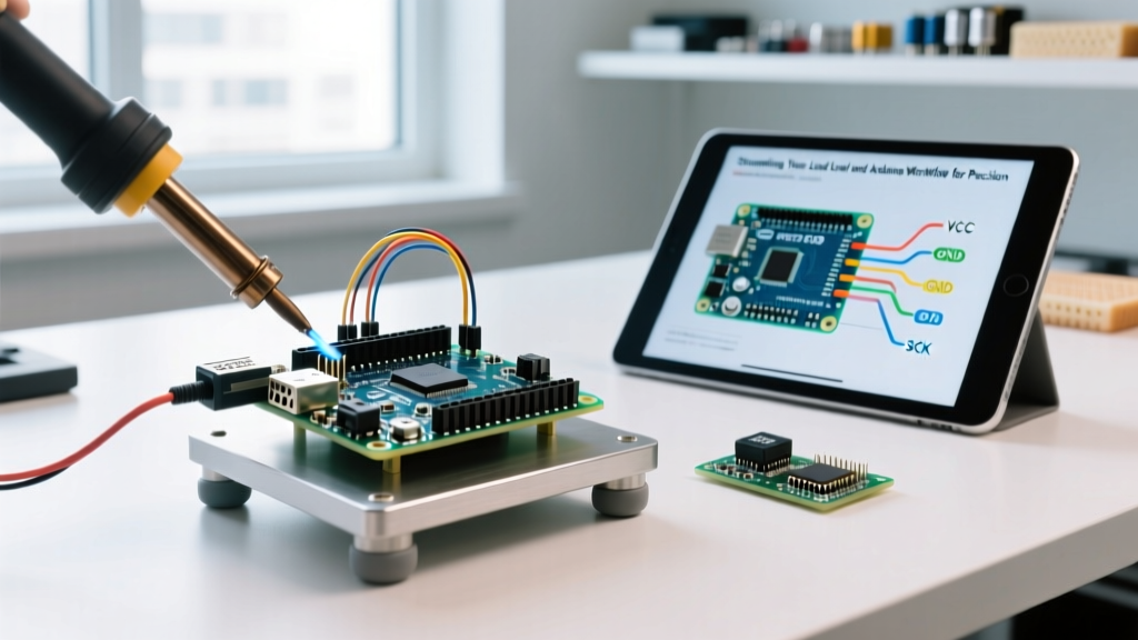
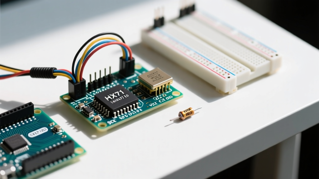
The HX711 acts as the intermediary between the microcontroller and the strain gauge. Below is the definitive wiring map for standard 4-wire load cells (like the CZL601 or S-Type sensors) to the HX711 breakout board and an Arduino Uno/Nano.
| HX711 Pin | Arduino Pin | Load Cell Wire (Standard Color) | Function & Notes |
|---|---|---|---|
| VCC | 5V (or 3.3V) | N/A | Power (Accepts 2.6V to 5.5V) |
| GND | GND | N/A | Common Ground |
| DT (DOUT) | D2 | N/A | Serial Data Out |
| SCK (PD_SCK) | D3 | N/A | Serial Clock In |
| E+ (VCC) | N/A | Red (Excitation +) | Bridge Power |
| E- (GND) | N/A | Black (Excitation -) | Bridge Ground |
| A+ (Signal+) | N/A | White (Signal +) | Amplifier Positive Input |
| A- (Signal-) | N/A | Green or Blue (Signal -) | Amplifier Negative Input |
Expert Warning: Never swap the Excitation (E+/E-) and Signal (A+/A-) wires. Applying 5V excitation directly into the high-impedance A+/A- amplifier inputs can permanently saturate or damage the HX711's internal Programmable Gain Amplifier (PGA).
Hardware Selection & Compatibility FAQs
Which load cell topology should I choose?
Your mechanical application dictates the topology. For DIY bathroom or kitchen scales, the CZL601 50kg Single-Point Aluminum load cell is the undisputed standard due to its low cost and integrated parallelogram flexure. For hopper weighing or tensile testing, an S-Type load cell (e.g., Talons T23 series) handles both tension and compression up to 500kg. For industrial platform scales exceeding 1000kg, you must use Shear Beam load cells mounted at four corners, summing their signals in parallel.
Why is the HX711 the industry standard for makers?
Microcontrollers like the Arduino Uno only have a 10-bit ADC, which is entirely insufficient for the microvolt-level signals outputted by a strain gauge. The HX711, manufactured by Avia Semiconductor, features a 24-bit Sigma-Delta ADC with an integrated PGA. It offers selectable gains of 128 or 64 on Channel A, and a fixed gain of 32 on Channel B. This allows the Arduino to read weight changes down to fractions of a gram without requiring external operational amplifiers or complex analog filtering circuits.
Calibration & Coding Quick-Reference
How do I calculate the exact calibration factor?
Every strain gauge has slight manufacturing variances in resistance and sensitivity (rated in mV/V). You cannot rely on hardcoded datasheet values. To calibrate, use the Bogdan Necula HX711 Library and follow this empirical process:
- Upload a sketch with
scale.set_scale()andscale.tare(). - Place a known reference weight on the scale (e.g., a calibrated 1kg dumbbell or a sealed 1-gallon jug of water which weighs exactly 3.785 kg).
- Read the raw uncalibrated output via
scale.get_units(10). Suppose it reads421500. - Divide the raw reading by your known weight in your desired unit. (e.g.,
421500 / 1000g = 421.5). - Update your code with
scale.set_scale(421.5).
Why does my tare function fail to zero out the scale?
The tare() function simply reads the current ADC value and stores it as an offset. If your mechanical mount is still settling (creep), or if the HX711 is experiencing thermal drift from a recent power-on, the tare value will be inaccurate. Best Practice: Implement a software delay of 2 seconds after power-on before calling tare(20) (averaging 20 samples) to allow the analog circuitry to stabilize.
Troubleshooting Drift, Noise, and Spikes
Why are my readings fluctuating by hundreds of grams?
Wild fluctuations are almost always caused by 50Hz or 60Hz AC mains hum coupling into the high-impedance analog traces. By default, many HX711 breakout boards are configured to sample at 80 Samples Per Second (SPS). At this rate, the ADC's internal digital filter is not optimized to reject mains frequency interference.
The Fix: Locate the RATE pin on the HX711 IC (Pin 15). On most breakout boards, there is a jumper pad near the IC. Bridge this pad to GND. This forces the ADC into 10 SPS mode, which activates a deep internal notch filter specifically designed to reject 50/60Hz noise. Your readings will instantly stabilize, though your maximum refresh rate will drop to 10Hz, which is perfectly adequate for weighing applications.
Why do my readings drift upward over time?
If your scale reads 0g, but slowly climbs to 15g over ten minutes without any weight added, you are experiencing mechanical creep or thermal EMF drift.
1. Mechanical Creep: The aluminum or steel flexure deforms slightly under constant load and takes time to return to zero. Always design your mount to allow the load cell to 'rest' when not in use.
2. Thermal Drift: The HX711 generates a small amount of internal heat. If your load cell wires are unshielded and routed near the HX711 chip or a voltage regulator, thermal gradients will generate microvolt thermocouple effects at the solder joints. Keep the HX711 physically separated from the load cell flexure.
Advanced Maker Tips for 24-Bit Precision
To extract true 24-bit precision from your Arduino load cell setup, mechanical mounting is just as critical as electrical wiring. Single-point aluminum load cells rely on a specific parallelogram flexure design. A catastrophic mistake made by beginners is mounting the load cell directly flat against a rigid wooden or metal base without standoffs. If your top and bottom mounting plates touch, or if the flexure gap is closed, you bypass the strain gauge entirely, resulting in a completely unresponsive sensor.
Always use the included rubber or metal spacers to ensure a minimum 2mm gap between the load cell beam and the mounting plates. Furthermore, torque your mounting bolts evenly using a calibrated driver; uneven torque introduces torsional stress into the aluminum beam, which manifests as severe zero-point drift and hysteresis. For environments with heavy EMI (like near stepper motors or VFDs), use shielded twisted-pair (STP) cable for the load cell extension, and connect the shield drain wire to the Arduino GND at one end only to prevent ground loops. For deeper integration strategies, refer to the SparkFun HX711 Hookup Guide for advanced breakout board modifications.