
The Bottleneck in Standard Load Cell Workflows
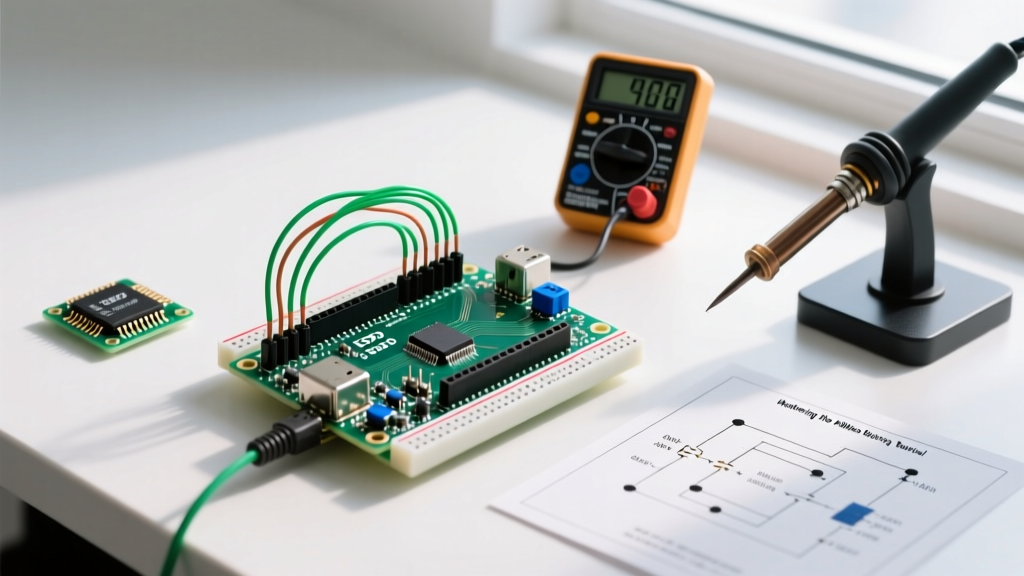
Integrating a load cell and Arduino microcontroller is a foundational skill for makers building digital scales, robotic grippers, or industrial force-feedback systems. However, the default workflow—often copied from outdated 2018-era tutorials—is riddled with inefficiencies. Standard implementations rely on blocking code that halts the main loop for up to 100 milliseconds per reading, ignore persistent calibration, and fail to address the analog noise floor inherent in 24-bit ADCs.
As of 2026, modern maker projects demand higher throughput, lower power consumption, and sub-gram precision. Whether you are using a cheap 50kg CZL601 half-bridge sensor or a precision 100g LSP-1 single-point beam, optimizing your hardware selection and software architecture is non-negotiable. This guide deconstructs the traditional load cell workflow and replaces it with a streamlined, non-blocking, and highly calibrated methodology.
Hardware Matrix: Selecting the Right 24-Bit ADC
The Wheatstone bridge output of a typical strain gauge load cell is in the millivolt range, requiring a dedicated instrumentation amplifier. While the Avia Semiconductor HX711 has been the undisputed king of budget projects, the 2026 component landscape offers superior alternatives depending on your workflow constraints.
| Amplifier Module | Avg. Price (2026) | Interface | Sample Rate | Workflow Verdict |
|---|---|---|---|---|
| Generic HX711 Breakout | $2.50 - $4.00 | Custom SPI-like | 10 or 80 SPS | Best for ultra-budget, single-task scales. Requires manual level-shifting for 3.3V MCUs. |
| SparkFun Qwiic HX711 | $14.95 | Qwiic (I2C) / SPI | 10 or 80 SPS | Optimal for rapid prototyping. Onboard ATTiny handles I2C translation, eliminating blocking reads. |
| Adafruit NAU7802 | $9.95 | True I2C | 10 to 320 SPS | The 2026 standard for battery-powered IoT. True I2C, internal LDO, and non-blocking register polling. |
Workflow Step 1: Implementing Non-Blocking Read Architectures
The most common mistake when pairing a load cell and Arduino is using the standard HX711.read() function inside the main loop(). This function waits for the DOUT pin to go LOW, effectively pausing your entire microcontroller. At the default 10 SPS (Samples Per Second) rate, your MCU is blind to button presses, network packets, or motor encoders for 10% of its runtime.
The State-Machine Polling Method
To optimize your workflow, decouple the hardware readiness from your application logic. By polling the is_ready() state or utilizing hardware interrupts, you maintain a responsive system. Below is the architectural pattern for a non-blocking read:
// Non-blocking HX711 polling pattern
unsigned long lastWeightRead = 0;
const unsigned long readInterval = 100; // 10 SPS = 100ms

void loop() {
  // 1. Check if ADC has finished conversion
  if (digitalRead(HX711_DOUT_PIN) == LOW) {
    if (millis() - lastWeightRead >= readInterval) {
      long rawValue = scale.read(); // Read only when ready
      processWeightData(rawValue);
      lastWeightRead = millis();
    }
  }

  // 2. Execute other critical tasks (WiFi, UI, Motors)
  handleNetworkStack();
  updateDisplay();
}
For advanced users working with the NAU7802 via I2C, you can configure the DRDY (Data Ready) interrupt pin to trigger an ISR (Interrupt Service Routine) that simply sets a volatile boolean flag, ensuring zero CPU cycles are wasted on polling.
Workflow Step 2: Persistent Calibration via EEPROM
Recalibrating your scale every time the Arduino reboots destroys development momentum and ruins the end-user experience. A robust workflow embeds the calibration factor and tare offset directly into the microcontroller's non-volatile memory.
Storing Floats and Longs Safely
The calibration factor (usually a float between 400.0 and 42000.0 depending on your load cell's mV/V rating) and the tare offset (a long integer representing the zero-point) must survive power cycles. According to the Arduino EEPROM Documentation, using EEPROM.put() and EEPROM.get() is the most efficient way to handle multi-byte variables without manual bitwise shifting.
- Step A: Place a known calibration mass (e.g., a certified 1kg steel weight) on the sensor.
- Step B: Trigger a 'Calibrate' routine via a physical button or serial command.
- Step C: Calculate the factor:
calibration_factor = (raw_average - tare_offset) / known_mass. - Step D: Write to EEPROM:
EEPROM.put(0, calibration_factor); EEPROM.put(4, tare_offset);.
Pro-Tip for Flash Wear: EEPROM has a limited lifespan of ~100,000 write cycles. Never write to EEPROM inside your main loop. Only commit values when the user explicitly initiates a calibration sequence or when the device enters a dedicated configuration mode.
Workflow Step 3: Hardware-Level Noise Mitigation
A 24-bit ADC like the HX711 can theoretically resolve down to a fraction of a gram, but electromagnetic interference (EMI) and thermal drift will quickly reduce your effective number of bits (ENOB) to 12 or 14. As detailed in Omega Engineering's Load Cell Technical Guide, environmental factors are the primary enemy of precision strain measurements.
Optimizing the RATE Pin for Mains Rejection
The generic HX711 module features a RATE pin. Most tutorials ignore this, leaving it floating or defaulted to 80 SPS. If your project operates in an environment with 50Hz or 60Hz AC mains power (near HVAC systems, LED drivers, or relays), you must tie the RATE pin to GND. This forces the ADC into 10 SPS mode, which engages the internal digital filter's notch at 50/60Hz, dramatically reducing common-mode AC hum.
Wiring and Grounding Topologies
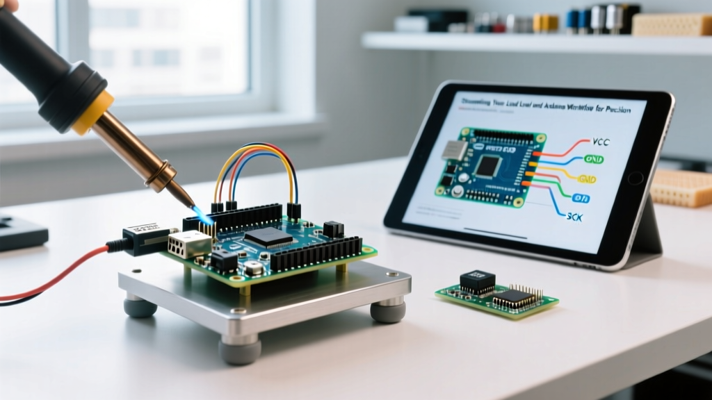
To prevent the Arduino's digital switching noise from corrupting the analog signal, implement the following physical workflow rules:
- Twisted Pairs: Always twist the
E+andE-(Excitation) wires together, and theA+andA-(Signal) wires together. This ensures that any external magnetic fields induce equal and opposite voltages, which the instrumentation amplifier rejects. - Star Grounding: Do not daisy-chain your load cell ground with high-current components like stepper motors or relays. Route the load cell
GNDdirectly to the Arduino's primary ground pin. - PWM Isolation: Keep PWM-driven motor controller lines at least 5cm away from the HX711 analog traces. The high dV/dt of PWM edges easily couples into high-impedance strain gauge traces.
Advanced Edge Cases: Thermal Drift and Creep
Even with perfect code and wiring, physics will challenge your workflow. Aluminum beam load cells (like the popular CZL601) exhibit thermal zero drift, typically around 0.02% of Full Scale Output (FSO) per °C. If your Arduino is mounted inside an enclosed 3D-printed ABS case where internal temperatures rise by 15°C during operation, your zero-point will shift.
To optimize for this, integrate a cheap I2C temperature sensor (like the TMP117 or BME280) into your workflow. By logging the temperature alongside the raw ADC data during your initial calibration phase, you can derive a software compensation curve. For mission-critical 2026 applications, SparkFun's HX711 Hookup Guide recommends allowing the system to 'warm up' for 3 to 5 minutes before executing the final tare() routine, ensuring the silicon and the aluminum beam have reached thermal equilibrium.
Summary: The Optimized Maker Pipeline
Transitioning from a hobbyist approach to an optimized engineering workflow transforms the load cell and Arduino combination from a frustrating, noisy experiment into a reliable, precision instrument. By selecting the right I2C-based ADC, implementing non-blocking state machines, persisting calibration data to EEPROM, and respecting analog grounding topologies, you eliminate 90% of the debugging time traditionally associated with force-sensing projects.