
The Silicon Reality: Beyond the Arduino Brand
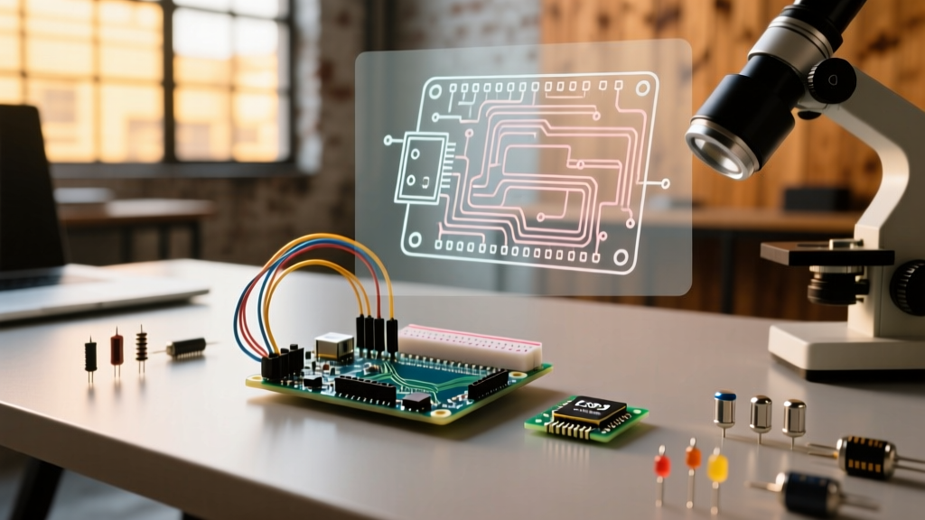
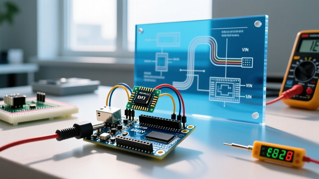
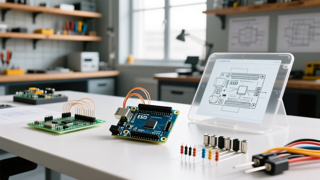
When embedded engineers and hobbyists first ask, 'what microcontroller does Arduino use?', they are typically looking for a simple part number like the ATmega328P. However, treating 'Arduino' as a single hardware entity is a critical mistake that leads to inefficient development workflows, bloated firmware, and frustrating debugging sessions. Arduino is an ecosystem, a bootloader standard, and an IDE wrapper that sits on top of vastly different silicon architectures.
As of 2026, the Arduino lineup spans 8-bit AVR, 32-bit ARM Cortex-M, Renesas RA, and Espressif RISC-V/Xtensa architectures. Understanding the exact microcontroller unit (MCU) executing your code is the foundational step in workflow optimization. It dictates your toolchain selection, memory management strategies, and debugging paradigms. This guide breaks down the silicon inside modern Arduino boards and provides actionable strategies to optimize your development pipeline from prototype to production.
Comparative Matrix: What Microcontroller Does Arduino Use in 2026?
To optimize your workflow, you must first map the board to its underlying silicon. The table below outlines the core microcontrollers used in the most popular Arduino boards available today, highlighting the architectural differences that impact compilation and execution.
| Arduino Board | Core Microcontroller | Architecture | Clock Speed | Flash / SRAM | Primary Toolchain |
|---|---|---|---|---|---|
| Uno R3 / Nano | Microchip ATmega328P | 8-bit AVR | 16 MHz | 32 KB / 2 KB | avr-gcc |
| Uno R4 Minima | Renesas RA4M1 | 32-bit ARM Cortex-M4 | 48 MHz | 256 KB / 32 KB | arm-none-eabi-gcc |
| Nano 33 IoT | Microchip SAMD21G18A | 32-bit ARM Cortex-M0+ | 48 MHz | 256 KB / 32 KB | arm-none-eabi-gcc |
| Nano ESP32 | Espressif ESP32-S3 | 32-bit Xtensa LX7 / RISC-V | 240 MHz | 8 MB / 512 KB | xtensa-esp32s3-elf-gcc |
| Mega 2560 | Microchip ATmega2560 | 8-bit AVR | 16 MHz | 256 KB / 8 KB | avr-gcc |
Source: Official Arduino Documentation and manufacturer datasheets.
Optimizing the Toolchain: Compiler Flags and Build Times
The answer to 'what microcontroller does Arduino use' directly determines your compiler. The Arduino IDE abstracts this away, but for workflow optimization, migrating to a platform like PlatformIO or a custom VS Code CMake setup is essential. Different MCUs respond differently to compiler optimization flags.
AVR (ATmega) vs. ARM/Espressif Toolchains
For 8-bit AVR chips like the ATmega328P, flash space is at a premium. The default Arduino compiler flag is -Os (optimize for size). However, you can significantly reduce binary size by enabling Link Time Optimization (LTO). In your platformio.ini or Makefile, adding -flto to the build flags can shave 10% to 15% off your final hex file size, which is critical when you are hovering near the 32KB limit.
Conversely, for 32-bit ARM Cortex-M4 chips like the Renesas RA4M1 on the Uno R4, flash is abundant (256KB), but execution speed and DSP operations matter more. Switching the optimization flag from -Os to -O2 or -O3 enables aggressive loop unrolling and inline expansion. This increases binary size but drastically reduces execution time for math-heavy sensor fusion algorithms.
Pro Tip: If you are compiling large ESP32-S3 projects, enable
CONFIG_COMPILER_OPTIMIZATION_PERFin the ESP-IDF menuconfig. The dual-core 240 MHz Xtensa architecture thrives on instruction-level parallelism, and default size-optimization will bottleneck your RTOS tasks.
Memory Allocation and Bootloader Bypass Strategies
A major hidden bottleneck in the standard Arduino workflow is the bootloader. The bootloader is a small program residing in a protected section of the MCU's flash memory that listens for serial data to upload new sketches. Knowing your exact MCU allows you to manage this overhead.
- ATmega328P (Uno/Nano): Uses the Optiboot bootloader, which consumes exactly 512 bytes (0.5 KB) of flash. While small, it also reserves the first 512 bytes of memory and introduces a ~500ms delay on every hard reset.
- SAMD21 & RP2040: These utilize UF2 bootloaders mapped to separate ROM or hidden flash partitions. They do not eat into user flash, but they rely on USB mass-storage enumeration, which can take 2-3 seconds to mount on host OS systems.
- ESP32-S3: Uses a multi-stage bootloader (ROM bootloader + Secondary Bootloader) that manages complex flash partitioning (OTA, SPIFFS, NVS).
The Production Workflow: ISP and SWD Bypass
If you are moving from prototyping to a production run of 50+ units, the standard serial bootloader workflow is far too slow. For AVR boards, you should bypass the bootloader entirely using an In-System Programmer (ISP) like the USBasp or Atmel-ICE. This reclaims the 512 bytes of flash and eliminates the boot delay. For ARM-based boards like the Nano 33 IoT, you utilize the Serial Wire Debug (SWD) pins to flash the binary directly via OpenOCD, achieving programming speeds upwards of 100 KB/s compared to the ~15 KB/s limit of the UART serial bootloader.
Hardware Debugging: Moving Past Serial.print()
The most significant workflow upgrade you can make is abandoning Serial.print() for debugging. The capability to use hardware debugging depends entirely on the microcontroller architecture.
Setting up SWD/JTAG for Cortex-M Boards
Boards utilizing the SAMD21, Renesas RA4M1, or STM32 architectures support hardware debugging via the SWD (Serial Wire Debug) interface. By connecting a CMSIS-DAP compatible probe (like a Raspberry Pi Picoprobe, which costs under $10, or a Segger J-Link EDU for ~$60), you can achieve true step-through debugging.
Using the Cortex-Debug extension in VS Code, you can:
- Set conditional breakpoints inside hardware interrupt service routines (ISRs) without crashing the MCU timing.
- Inspect peripheral registers (e.g., viewing the exact state of the I2C status register in real-time).
- Profile CPU cycles to identify exactly which function is consuming the most processing time.
Note: The classic ATmega328P does not support SWD. It requires a debugWIRE interface, which is notoriously difficult to configure in modern IDEs. If hardware debugging is a strict requirement for your workflow, you must migrate to an ARM-based Arduino board.
Workflow Decision Framework: Prototyping to Production
Understanding the silicon allows you to select the right board for the right phase of your project lifecycle. Use this decision matrix to optimize your hardware selection:
- Rapid Prototyping (Low I/O): Arduino Nano (ATmega328P). Best for simple state machines, basic sensor reading, and leveraging the massive library of legacy 8-bit code. Toolchain compiles in seconds.
- DSP & Motor Control: Arduino Uno R4 Minima (Renesas RA4M1). The Cortex-M4 includes a hardware Floating Point Unit (FPU) and DSP instructions. Use this when your workflow requires heavy PID calculations or Kalman filtering without software emulation overhead.
- IoT & Edge ML: Arduino Nano ESP32 (ESP32-S3). Required if your workflow integrates Wi-Fi/BLE or TinyML. The vector instructions on the S3 accelerate TensorFlow Lite Micro inference tasks by orders of magnitude compared to AVR.
Summary
Asking 'what microcontroller does Arduino use' is the gateway to professional embedded development. By mapping your project requirements to the specific architectural strengths of the ATmega328P, Renesas RA4M1, SAMD21, or ESP32-S3, you eliminate guesswork. Transitioning to architecture-specific toolchains, leveraging Link Time Optimization, bypassing bootloaders for production, and utilizing SWD hardware debugging will transform your workflow from a hobbyist trial-and-error loop into a precise, optimized engineering pipeline.
For deep dives into specific MCU registers and peripheral configurations, always refer to the Microchip ATmega328P Datasheet or the respective ARM technical reference manuals, as the Arduino core libraries only scratch the surface of what these chips can truly do.