
The 2026 Logic Level Bottleneck: 5V vs 3.3V Architectures
As of 2026, the maker ecosystem has decisively shifted toward 3.3V logic architectures. With the dominance of the Raspberry Pi RP2040, ESP32-S3, and the Arduino Nano ESP32, the legacy 5V TTL standard of the original ATmega328P is no longer the default. However, the most ubiquitous and affordable motor drivers on the market remain designed for 5V logic. This creates a critical compatibility gap: connecting a 3.3V microcontroller directly to a 5V Arduino H-bridge often results in erratic motor behavior, missed PWM pulses, and thermal throttling.
This comprehensive compatibility guide breaks down the electrical characteristics of the most popular H-bridge ICs, mapping them to modern microcontrollers to ensure reliable torque, efficient switching, and hardware longevity.
H-Bridge IC Compatibility Matrix
Before wiring up your next robotics chassis or conveyor prototype, consult this matrix to match your motor driver with the appropriate MCU logic family and power supply.
| H-Bridge IC | Architecture | Max Continuous Current | Logic Voltage ($V_{IH}$) | Voltage Drop | Best MCU Match |
|---|---|---|---|---|---|
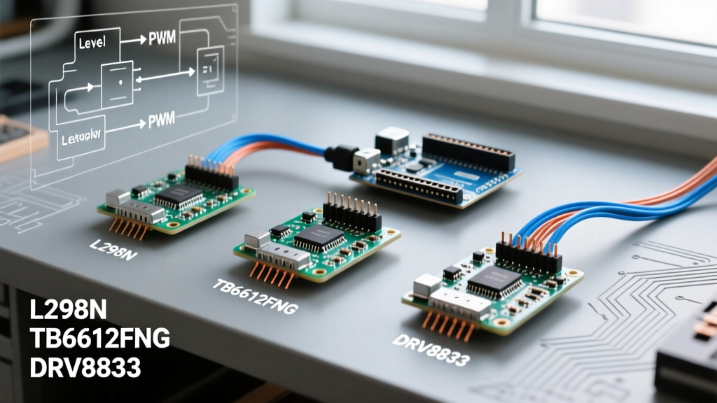
| L298N | Bipolar (BJT) | 2.0A per channel | 2.3V - 5V (5V ideal) | 1.8V - 3.2V | Arduino Uno R3, Mega 2560 (5V) |
| TB6612FNG | MOSFET | 1.2A per channel | 2.0V - 5.5V | ~0.5V ($R_{DS(on)}$) | ESP32, RP2040, Nano 33 BLE (3.3V) |
| DRV8833 | NMOS (TI) | 1.5A per channel | 1.3V - 5.25V | ~0.6V | ESP32, Arduino Nano ESP32 (3.3V) |
| BTS7960 | High-Power MOSFET | 43A (theoretical) | 5.5V threshold (strict) | Very Low | Arduino Mega 2560 (Requires Level Shifter for 3.3V) |
Deep Dive: Legacy vs. Modern H-Bridge Modules
The L298N: Bipolar Limitations and Voltage Starvation
The L298N is the most recognized STMicroelectronics motor driver in DIY kits. However, its bipolar junction transistor (BJT) design is fundamentally outdated for low-voltage battery applications. Because it uses Darlington pairs internally, it suffers from a massive voltage drop—typically between 1.8V and 3.2V depending on the current draw.
The Compatibility Flaw: If you power an L298N module with a standard 2S LiPo (7.4V nominal), your motors will only see roughly 5.4V. Furthermore, the L298N requires an Input High Voltage ($V_{IH}$) of at least 2.3V to register a logic '1'. While a 3.3V ESP32 output technically exceeds 2.3V, it sits dangerously close to the threshold. In environments with electromagnetic interference (EMI) from the motors themselves, this narrow noise margin causes phantom triggering and PWM jitter.
TB6612FNG & DRV8833: The MOSFET Standards for 3.3V MCUs
For modern 3.3V microcontrollers, MOSFET-based drivers are mandatory. The Toshiba TB6612FNG and the Texas Instruments DRV8833 utilize low $R_{DS(on)}$ MOSFETs, which drastically reduces the voltage drop to under 0.6V. This means a 6V battery pack delivers nearly the full 6V to the motor terminals, resulting in significantly higher torque and RPM.
More importantly, their logic thresholds are highly compatible with 3.3V MCUs. The DRV8833, for instance, guarantees a logic '1' recognition at just 1.3V, making it completely immune to noise when driven by an RP2040 or ESP32-S3. When building autonomous rovers in 2026, the TB6612FNG should be your default choice for motors drawing under 1.2A.
BTS7960: High-Current Heavy Lifting and Logic Thresholds
When moving beyond small DC gearmotors into heavy-duty applications like electric wheelchairs, large winches, or combat robotics, the BTS7960 module is the go-to solution. Capable of handling massive continuous currents (realistically 20A-30A with active cooling, despite the 43A datasheet claim), it requires careful logic integration.
Warning: The BTS7960 logic enable pins often feature optocouplers or voltage divider networks on cheap breakout boards that require a strict 5V logic high to activate. Connecting a 3.3V Arduino Nano ESP32 directly to the 'R_EN' and 'L_EN' pins will result in a disabled H-bridge. You must use a bidirectional logic level translator (like the TXB0104 or a simple BSS138 MOSFET shifter) to bridge the 3.3V MCU to the 5V BTS7960 control pins.
PWM Frequency Mismatches and Switching Losses
Compatibility is not just about voltage levels; it is also about timing. Microcontrollers output Pulse Width Modulation (PWM) at varying default frequencies, which directly impacts H-bridge thermal performance.
- Arduino Uno (ATmega328P): Default PWM is ~490Hz. This is perfectly suited for the slower switching speeds of the L298N.
- ESP32 (LEDC Peripheral): Default PWM is often configured to 5000Hz (5kHz). While great for LEDs, pushing 5kHz into an L298N causes massive switching losses. The BJT transistors spend too much time in the linear (active) region during transitions, generating extreme heat and reducing efficiency by up to 40%.
- Raspberry Pi Pico (RP2040): Highly configurable, but often set to high frequencies in MicroPython/C++ wrappers.
Actionable Fix: When using MOSFET drivers like the DRV8833 with an ESP32, a 5kHz PWM is acceptable. However, if you are forced to use an L298N with a modern MCU, you must manually configure your PWM timers to output between 500Hz and 1kHz to minimize switching heat. Additionally, frequencies above 20kHz are recommended only if you need to eliminate audible motor whine, provided your H-bridge supports fast gate charging.
Expert Callout: Decoupling and Flyback Protection
Never rely solely on the H-bridge's internal flyback diodes for high-inductance motors. Internal diodes often have slow reverse recovery times ($t_{rr}$). For motors drawing >2A, solder a Schottky diode (e.g., 1N5819) directly across the motor terminals, and place a 100nF ceramic capacitor in parallel with a 470µF low-ESR electrolytic capacitor at the H-bridge power input. This prevents inductive kickback from resetting your 3.3V MCU's brown-out detector (BOD). For deeper insights into motor inductive loads, refer to SparkFun's H-Bridge Basics tutorial.
Wiring and PCB Trace Considerations for Makers
If you are migrating from a breadboard prototype to a custom PCB in 2026, trace width dictates your H-bridge compatibility. A standard 10-mil (0.25mm) trace on 1oz copper can only safely carry about 0.5A before experiencing dangerous temperature rises.
When routing a TB6612FNG or DRV8833, ensure your power and ground traces are at least 40-mil to 60-mil wide for the 1.2A to 1.5A channels. For BTS7960 high-current paths, you must use 2oz copper with traces exceeding 200-mil (5mm), and ideally apply solder mask relief to allow for manual solder flooding over the high-current traces.
Frequently Asked Questions (FAQ)
Can I power a 5V Arduino H-bridge module directly from a 3.7V LiPo battery?
No. Most 5V H-bridge modules (especially those with onboard 7805 linear regulators for the logic IC) require a minimum input voltage of 6V to 7V to properly regulate the 5V logic rail. If you supply 3.7V, the logic IC will brown out, and the motor will not spin. Use a boost converter (like the MT3608) to step the 3.7V LiPo up to 7V before entering the H-bridge module's VCC terminal.
Why does my ESP32 keep resetting when the H-bridge engages?
This is a classic ground bounce and voltage sag issue. When a DC motor starts, it draws stall current (often 5x to 10x the running current). This massive current draw causes the shared ground potential to spike and the battery voltage to sag, triggering the ESP32's internal Brown-Out Detection (BOD). Separate your logic ground and motor ground, joining them at a single 'star ground' point near the power supply, and add bulk capacitance (1000µF+) to the battery terminals.
Is the Arduino Motor Shield V3 compatible with 3.3V boards?
Modern iterations of motor shields utilizing the DRV8833 or similar TI/NXP MOSFET drivers are fully compatible with 3.3V logic boards like the Arduino Nano ESP32 and Nano 33 IoT. However, always verify the shield's schematic to ensure the onboard logic buffers (if present) are not hardcoded to 5V TTL thresholds.