
The Diagnostic Matrix: Symptom to Solution
Building a motor arduino project is a rite of passage for makers, but few things are as frustrating as uploading your sketch only to be met with silence, a faint clicking, or an unexpected microcontroller reset. Before you rewrite your code or desolder your connections, use this diagnostic matrix to isolate the exact failure point in your DC motor circuit.
| Symptom | Probable Cause | Quick Fix |
|---|---|---|
| Motor twitches or hums but won't spin | Insufficient stall current / Voltage sag | Upgrade power supply; abandon 9V PP3 batteries. |
| Motor spins in one direction only | Blown H-bridge half or dead logic pin | Swap IN1/IN2 pins; test with multimeter. |
| Arduino resets when motor starts | Back-EMF spike or shared ground noise | Add flyback diodes; isolate logic power. |
| Motor spins but extremely slowly/weakly | L298N voltage drop or PWM pin error | Switch to MOSFET driver (TB6612FNG); verify PWM pin. |
| Nothing happens; driver IC gets burning hot | Shorted motor windings or over-current | Check motor continuity; verify stall current limits. |
1. The Power Starvation Trap (Why 9V Batteries Fail)
The single most common reason a motor arduino setup fails to spin is inadequate current delivery. Many beginners power their DC motors using standard rectangular 9V PP3 batteries. While a 9V battery has the correct voltage for a 6V-9V DC motor, it completely lacks the current capacity and suffers from high internal resistance (often 1 to 2 ohms).
When a DC motor starts, it draws stall current, which can be 5 to 10 times higher than its running current. If your motor has a running current of 300mA, its stall current might be 1.5A. Pushing 1.5A through a 9V battery causes the voltage to instantly collapse below the minimum threshold required by both the motor and the driver IC's logic gates.
The Fix: High-Discharge Power Sources
- 18650 Li-Ion Cells: Two 18650 cells in series (2S) provide 7.4V nominal (8.4V fully charged) and can easily deliver 10A+ continuous current. A high-quality cell like the Samsung 25R costs around $5-$7 and will completely transform your project's reliability.
- LiPo Battery Packs: A 2S (7.4V) or 3S (11.1V) RC LiPo battery offers massive current delivery (look for 20C discharge ratings or higher).
- Benchtop Power Supply: For prototyping, use an adjustable bench supply set to the motor's rated voltage with the current limit set safely above the stall current (e.g., 3A).
2. Logic Level Mismatches: 3.3V vs 5V Microcontrollers
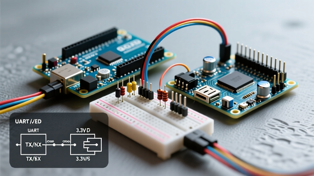
If you are using an ESP32, Raspberry Pi Pico, or Arduino Due, your microcontroller outputs 3.3V logic. However, the ubiquitous and incredibly cheap L298N motor driver module (typically $3 to $5 online) relies on older bipolar transistor technology that often requires a solid 5V HIGH signal to reliably trigger the internal optocouplers and H-bridge gates.
When fed 3.3V, the L298N may interpret the signal as a LOW, or it might enter a linear (partially on) state, causing the IC to overheat rapidly while delivering almost zero power to the motor.
The Fix: Match the Driver to the Logic
Instead of adding a bulky logic level converter (like the Texas Instruments SN74LVC8T245), simply upgrade your motor driver to a modern MOSFET-based IC that natively accepts 3.3V logic. According to the SparkFun TB6612FNG Hookup Guide, this modern driver operates flawlessly with logic voltages ranging from 2.7V to 5.5V, while also eliminating the massive 2V voltage drop inherent to the L298N.
3. Grounding Loops and Back-EMF Resets
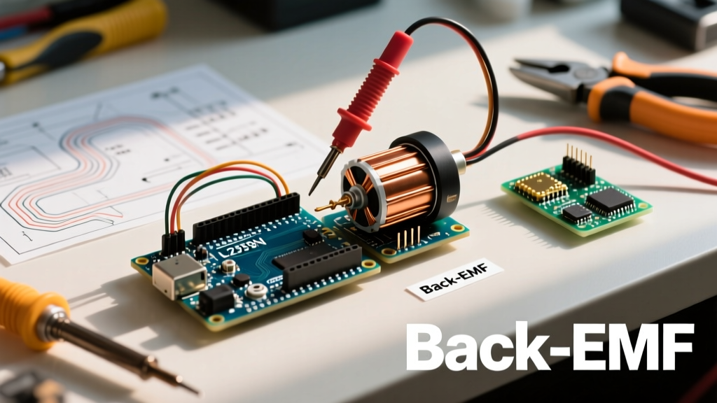
Does your Arduino randomly reboot or freeze the moment the motor engages? This is a classic symptom of Back-Electromotive Force (Back-EMF) or ground bounce. DC motors are essentially generators when they spin down or change direction. They send high-voltage spikes back into the circuit. If your motor driver lacks adequate protection, or if your wiring is too thin, this noise travels straight into the Arduino's 5V rail or reset pin.
The Mandatory Flyback Diode Rule
While most modern driver boards (like those based on the DRV8871 or TB6612FNG) include built-in clamping diodes, cheap clone boards often omit them or use diodes that are too slow to handle the spike. Always verify your hardware. For raw H-bridge setups or relay-driven motors, you must place a Schottky diode (like the 1N5819) in reverse bias across the motor terminals.
Pro-Tip: Never route motor power and logic power through the same breadboard ground rails. Breadboard contacts have high resistance and inductance. Run a dedicated, thick ground wire (18 AWG or thicker) directly from the battery's negative terminal to the motor driver's GND, and use a separate, thinner wire to connect the driver's logic GND to the Arduino's GND. This star-grounding technique is detailed extensively in the Arduino Official Motor Guide.
4. Thermal Shutdown and Stall Current Limits
Every motor driver IC has a thermal shutdown threshold. The L298N, for example, is rated for 2A per channel, but this is a peak rating. Without a massive heatsink and active cooling, continuous current should be kept below 1.2A. If your mechanical load is too high (e.g., a robot stuck on a carpet), the motor stalls, current spikes to the maximum, and the IC's internal thermal protection kicks in, silently cutting power to prevent a fire.
To fix this, measure the actual current draw using a multimeter in series with the motor. If your stall current exceeds 1.5A, you must either:
- Reduce the mechanical load or gear ratio.
- Implement software-based current limiting (using an inline shunt resistor and an analog read pin).
- Upgrade to a higher-current driver, such as the BTS7960 (43A peak, ~$12) or a VNH5019 shield, as recommended by Texas Instruments Motor Drivers documentation for heavy inductive loads.
5. Step-by-Step Multimeter Verification
Stop guessing and start measuring. Follow this exact sequence with a digital multimeter (DMM) to isolate your motor arduino failure:
- Verify Power at the Source: Set DMM to DC Voltage. Measure directly across the battery terminals while the motor is trying to spin. If voltage drops below 70% of nominal, your battery is dead or undersized.
- Verify Power at the Driver: Measure the VCC and GND pins on the motor driver board. Ensure it matches the battery voltage.
- Verify Logic Signals: Set DMM to DC Voltage. Probe the IN1 and IN2 pins on the driver while the Arduino sketch is running. You should see ~5V (or 3.3V) on the active pin and ~0V on the inactive pin. If you see 0V on both, your code or wiring is wrong.
- Verify PWM Output: Set DMM to AC Voltage (or frequency if your meter supports it). Probe the ENA/ENB pin. A standard DC voltage reading will only show an average (e.g., 2.5V for 50% duty cycle). If it reads 0V, ensure you are using an actual hardware PWM pin on your Arduino (Pins 3, 5, 6, 9, 10, 11 on the Uno R3).
- Verify Output to Motor: Set DMM to DC Voltage. Probe the OUT1 and OUT2 terminals. If you have logic signals at IN1/IN2 but 0V at OUT1/OUT2, your driver IC is fried or in thermal shutdown.
Frequently Asked Questions (FAQ)
Can I power the Arduino and the motor from the same L298N 5V output?
Technically, the L298N module has an onboard 7805 voltage regulator that outputs 5V. However, this regulator is usually rated for only 500mA and is meant to power the board's own logic, not an entire Arduino Uno and a suite of sensors. Drawing too much current from this pin will cause the regulator to overheat and shut down, killing your microcontroller. Always power the Arduino via its own USB connection or barrel jack.
Why does my motor whine but not turn when using analogWrite()?
The high-pitched whine is the PWM frequency (typically 490Hz or 980Hz on Arduino) vibrating the motor windings. If it whines but doesn't spin, the duty cycle is too low to overcome the motor's static friction (stiction). Increase your analogWrite() value. Most small DC motors require a minimum PWM value of 60 to 80 (out of 255) just to start turning.