
The Hidden Costs of the 'Blink' Sketch
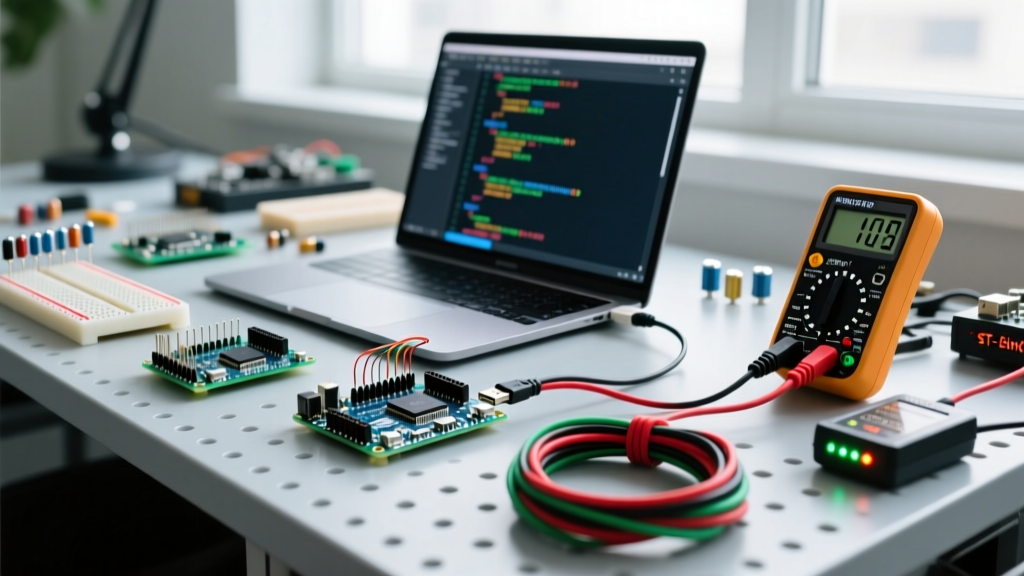
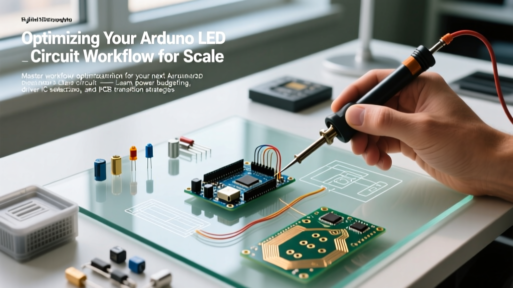
Every maker starts with a single 5mm LED and a 220-ohm resistor on a breadboard. It is the quintessential 'Hello World' of hardware. However, when your project evolves from a single indicator light to a multi-node array, a 16x16 matrix, or an architectural lighting installation, the standard prototyping workflow breaks down. Optimizing your arduino led circuit workflow is not just about writing cleaner code; it requires a fundamental shift in how you approach power delivery, component selection, and hardware abstraction.
In this guide, we will dismantle the hobbyist approach and rebuild a professional, scalable workflow for LED circuit design. By the end, you will know exactly how to transition from fragile breadboard prototypes to robust, manufactured PCBs without burning out your microcontroller or your budget.
Phase 1: Power Budgeting and Thermal Realities
The most common point of failure in intermediate LED projects is the Arduino’s onboard voltage regulator. Most genuine Arduino Uno R3 and R4 boards, as well as their third-party clones, utilize an NCP1117 or AMS1117 linear regulator to step down barrel-jack or USB voltage to 5V.
The AMS1117 Thermal Trap
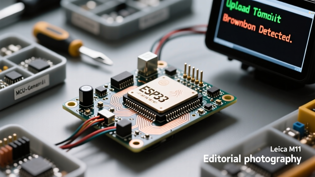
These linear regulators are typically rated for a maximum of 800mA to 1A. However, they lack adequate heatsinking on the PCB. If you power an array of 20 standard LEDs (each drawing 20mA, totaling 400mA) plus the ATmega328P's baseline draw of ~30mA, you are pulling nearly 500mA from the 5V rail. If you are stepping down from a 9V battery or a 12V wall adapter, the regulator must dissipate the excess voltage as heat. According to the AMS1117 datasheet, the thermal shutdown threshold is roughly 150°C. In a poorly ventilated enclosure, driving an LED array directly from the Arduino's 5V pin will trigger thermal throttling, causing the LEDs to flicker or the MCU to brownout and reset.
Workflow Optimization: Never route high-current LED arrays through the Arduino’s onboard 5V rail. Instead, use a dedicated buck converter or an enclosed switching power supply. A Mean Well RS-25-5 (5V, 5A) costs around $14 to $18 in 2026 and provides clean, isolated power. Wire the 5V and GND directly to your LED array's power bus, and connect only the ground and data lines back to the Arduino. This simple workflow change eliminates 90% of unexplained MCU reset issues.
Phase 2: Escaping the Breadboard Bottleneck
Breadboards are excellent for validating logic, but they are detrimental to signal integrity and current handling. Standard solderless breadboard contacts have a parasitic capacitance of roughly 2pF to 5pF per node and a contact resistance that can fluctuate between 0.1 and 0.5 ohms. When you attempt to push high-speed PWM signals or SPI data to shift registers for an LED matrix, this parasitic capacitance acts as a low-pass filter, rounding off your square waves and causing ghosting in your LED matrix.
Furthermore, breadboard power rails are typically rated for a maximum of 1A to 2A across the entire strip. Pushing 3A through a breadboard bus for a high-power RGB array will melt the internal metal clips, creating a severe fire hazard.
Workflow Optimization: Implement a 'quick-and-dirty' perfboard phase before committing to a custom PCB. Use 2.54mm pitch dot-perfboard and solder solid-core 22 AWG bus wires for your power rails. This reduces resistance to near-zero and allows you to validate your physical layout and wire routing before spending money on PCB fabrication.
Phase 3: Offloading the MCU with Dedicated Driver ICs
Driving LEDs directly from ATmega or ESP32 GPIO pins limits you to the MCU's I/O count and its per-pin current limits (typically 20mA to 40mA absolute maximum). To scale your arduino led circuit, you must offload the current switching to dedicated driver ICs. This optimizes your code workflow by allowing you to send high-level commands over I2C or SPI rather than bit-banging dozens of individual pins.
Below is a comparison of the three most effective driver architectures for scaling LED projects in 2026:
| Driver IC / Type | Best Use Case | Interface | Current Control | Approx. Cost (2026) |
|---|---|---|---|---|
| MAX7219 | 8x8 Dot Matrices, 7-Segment Displays | SPI | Single external resistor sets current for all digits | $1.50 - $2.50 |
| TLC5940 | High-res PWM individual LEDs, RGB mixing | SPI-like (SIN, SCLK, XLAT, GSCLK) | 16-channel constant current sink (up to 120mA/ch) | $2.00 - $3.00 |
| WS2812B (NeoPixel) | Addressable strips, complex 2D/3D shapes | Single-wire 800kHz protocol | Integrated constant-current driver inside the LED package | $0.02 - $0.05 per LED |
| ULN2803 | High-power 12V LED strips, relays | 8 Parallel GPIO pins | None (Requires external resistors/constant current supplies) | $0.50 - $0.80 |
By integrating a TLC5940, for example, you can control 16 individual LEDs with perfect 12-bit PWM dimming using only four wires. The Texas Instruments TLC5940 handles the constant-current sinking, meaning you no longer need to calculate and solder 16 individual current-limiting resistors, massively speeding up your assembly workflow.
Phase 4: Software Architecture for High-Density Arrays
When dealing with addressable LEDs like the WS2812B, the timing requirements are incredibly strict. The protocol requires precise 800kHz pulse trains. If your Arduino code pauses to read a sensor, check a serial buffer, or execute a standard delay() function, the data line drops low, and the LED strip will interpret this as a 'latch' signal, resulting in flickering or incomplete color updates.
To optimize your software workflow, you must decouple your rendering loop from your logic loop.
Implementing Non-Blocking State Machines
Instead of using blocking delays, utilize the FastLED library, which is heavily optimized for various AVR and ARM architectures. FastLED handles the strict timing interrupts automatically. Structure your code using non-blocking timers:
- Logic Loop: Runs continuously. Reads buttons, calculates color palettes, and updates an array in memory (e.g.,
CRGB leds[NUM_LEDS];). - Render Loop: Triggered only when the LED state actually changes, or capped at a specific refresh rate (e.g., 60 FPS) using
EVERY_N_MILLISECONDS(16).
For comprehensive wiring and timing insights on addressable arrays, the Adafruit NeoPixel ÜberGuide remains the gold standard for understanding the physical layer constraints of single-wire protocols.
Pro-Tip: Ground Bounce Mitigation
When driving long runs of WS2812B LEDs, the high-frequency switching can cause 'ground bounce'—a phenomenon where the local ground reference of the LED rises above the Arduino's ground, corrupting the data signal. Always inject power and ground at both ends of a strip exceeding 100 LEDs, and place a 470-ohm resistor on the data line as close to the first LED's DIN pin as possible to dampen high-frequency ringing.
Phase 5: Design for Manufacturing (DFM) in 2026
Once your perfboard prototype is stable, the final workflow optimization is transitioning to a custom PCB. In 2026, the barrier to entry for PCB fabrication is virtually non-existent. Services like JLCPCB and PCBWay offer 50x50mm 2-layer boards for under $3 for a batch of five, with assembly services that can solder surface-mount driver ICs for pennies per joint.
To optimize your DFM workflow in KiCad or Altium:
- Use Standard Footprints: Stick to 0805 or 1206 SMD resistors and capacitors. While 0402 saves space, it requires precision rework stations if you make a mistake during manual debugging.
- Thermal Vias: If you are using linear constant-current regulators (like the TLC5940 which dissipates heat equal to the voltage drop across its internal MOSFETs), place an array of 0.3mm thermal vias directly under the IC's exposed thermal pad to transfer heat to the ground plane on the bottom layer.
- Screw Terminal Placement: Place high-current power screw terminals (like Phoenix Contact MSTB series) near the edge of the board, and use a solid copper pour connected to multiple vias to handle the current load into the board's internal traces.
Frequently Asked Questions
Do I still need resistors if I use an LED driver IC?
It depends on the IC. Constant-current drivers like the TLC5940 or MAX7219 regulate the current internally based on a single master reference resistor connected to the IC's IREF pin. You do not need individual resistors for each LED. However, if you are using standard shift registers (like the 74HC595) or Darlington arrays (ULN2803), you must still use individual current-limiting resistors for every LED.
How thick should my PCB traces be for a 5A LED array?
According to standard IPC-2152 trace width calculators, a 1 oz copper trace on an external layer carrying 5A with a 10°C temperature rise requires a width of approximately 115 mils (2.9mm). For high-current LED arrays, always use 2 oz copper if your budget allows, which halves the required trace width and significantly reduces voltage drop across the board.
Can I power an Arduino and a large LED array from the same 5V source?
Yes, but you must manage the power sequencing. High-current LED arrays can cause massive inrush currents when they turn on, which can drag the 5V rail down to 4.2V for a few milliseconds. This brownout will reset the Arduino. To optimize this, add a large bulk capacitor (e.g., 1000µF to 2200µF, 10V) across the 5V and GND rails near the power injection point to absorb the inrush transient.