
Beyond Basic analogRead(): The Reality of ADC Impedance
Configuring an Arduino with potentiometer circuits is often the first analog task a maker tackles, but achieving true precision requires moving beyond the basic analogRead() tutorial. The analog-to-digital converter (ADC) inside microcontrollers like the ATmega328P (Arduino Uno R3) or the Renesas RA4M1 (Arduino Uno R4) relies on an internal sample-and-hold (S/H) capacitor—typically around 14pF. When the ADC multiplexer switches to your analog pin, this internal capacitor must charge to the exact voltage presented by your potentiometer's wiper within a fraction of an ADC clock cycle.
If the source impedance is too high, the capacitor cannot fully charge, resulting in non-linear readings that always skew lower than the actual voltage. According to the official Arduino analogRead() documentation, the recommended source impedance is 10kΩ or less. Using a 100kΩ potentiometer without buffering will introduce severe quantization errors, especially when multiplexing between multiple analog pins.
Hardware Selection: Choosing the Right Potentiometer
Not all potentiometers are created equal. The resistive element material dictates the component's noise floor, lifespan, and rotational torque. For precision MCU configurations, avoid cheap carbon composition pots; their wiper contact noise can cause ±15 LSB (Least Significant Bit) jumps on a 10-bit ADC.
| Material / Type | Model Example | Typical Price (2026) | Wiper Noise | Best Use Case |
|---|---|---|---|---|
| Carbon Composition | Generic Alpha 10kΩ | $0.30 - $0.80 | High (Crackling) | Basic LED dimming, non-critical UI |
| Cermet (Ceramic/Metal) | Bourns 3386 Series | $1.20 - $2.50 | Low | Calibration dials, sensor tuning, PID control |
| Conductive Plastic | Bourns 3590S Series | $12.00 - $18.00 | Ultra-Low | Audio mixing, robotic joint feedback, medical |
For a deep dive into industrial-grade component tolerances, the Bourns 3386 Cermet Trimmer Datasheet provides excellent baseline specifications for wiper contact resistance (typically <100mΩ) and end-to-end resistance tolerances (±10%).
Circuit Configuration: Hardware Low-Pass Filtering
Before writing a single line of smoothing code, you should implement a hardware low-pass filter. Mechanical wipers generate high-frequency contact bounce and thermal noise. By placing a 100nF (0.1µF) MLCC ceramic capacitor between the potentiometer's wiper pin and ground, you create a first-order RC low-pass filter.
Calculating the Cut-off Frequency
Assuming a 10kΩ potentiometer and a 100nF capacitor, the cut-off frequency ($f_c$) is calculated as:
$f_c = \frac{1}{2 \pi R C} = \frac{1}{2 \pi \times 10,000 \times 0.0000001} \approx 159 \text{ Hz}$
This effectively filters out high-frequency electrical noise and wiper bounce above 159Hz, presenting a clean DC voltage to the Arduino's ADC pin. Pro Tip: Keep the physical trace or wire length between the wiper and the analog pin as short as possible to minimize antenna effects from 50/60Hz mains hum.
Firmware Configuration: Exponential Moving Average (EMA)
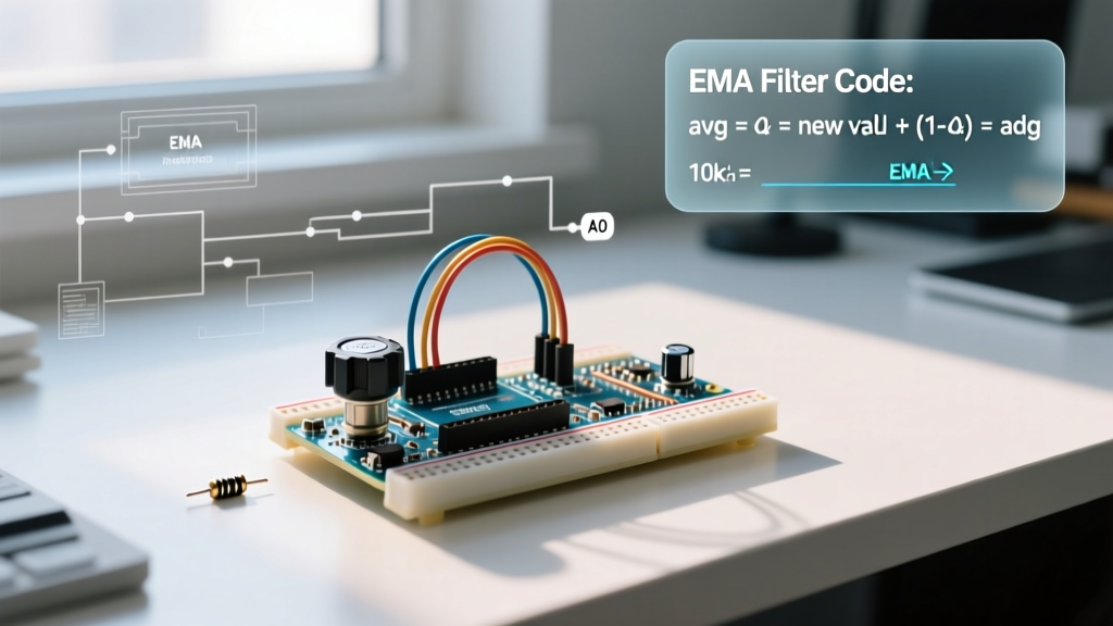
Even with hardware filtering, ADC quantization noise remains. Instead of using a Simple Moving Average (SMA) which requires storing an array of past values and consumes valuable SRAM, configure an Exponential Moving Average (EMA). The EMA applies a weighting factor (alpha) to the newest reading, requiring only a single floating-point or integer variable in memory.
// EMA Filter Configuration for Arduino with Potentiometer
const int POT_PIN = A0;
const float ALPHA = 0.15; // Smoothing factor (0.0 to 1.0). Lower = smoother but slower response.

float smoothedValue = 0.0;

void setup() {
  Serial.begin(115200);
  // Prime the filter with an initial reading to prevent startup lag
  smoothedValue = analogRead(POT_PIN);
}

void loop() {
  int rawReading = analogRead(POT_PIN);

  // EMA Calculation
  smoothedValue = (ALPHA * rawReading) + ((1.0 - ALPHA) * smoothedValue);

  // Map to a usable 0-255 PWM range
  int pwmOutput = map((int)smoothedValue, 0, 1023, 0, 255);

  Serial.print("Raw: ");
  Serial.print(rawReading);
  Serial.print(" | Smoothed: ");
  Serial.println(smoothedValue);

  delay(10); // 10ms sampling rate
}
Adjusting the ALPHA value allows you to tune the responsiveness. An alpha of 0.8 will track the potentiometer almost instantly but pass minor noise, while 0.05 will yield a buttery-smooth output at the cost of a 50-100ms physical lag.
Advanced: Oversampling for 12-Bit Resolution on 10-Bit ADCs
If you are using an Arduino Uno R3 (ATmega328P), you are limited to a 10-bit ADC (0-1023). However, you can mathematically configure the Arduino with potentiometer oversampling to achieve 12-bit resolution (0-4095) without changing hardware. This technique, heavily detailed in Analog Devices' application notes on ADC oversampling, relies on the presence of at least 1 LSB of random noise to dither the signal.
The Oversampling Algorithm
To gain $n$ additional bits of resolution, you must sample the signal $4^n$ times. To gain 2 extra bits (10-bit to 12-bit), you need $4^2 = 16$ samples.
- Read the analog pin 16 times in rapid succession.
- Sum all 16 readings (the sum will be up to 16,368, requiring a 16-bit unsigned integer).
- Bit-shift the sum right by 2 (divide by 4).
This yields a highly stable 12-bit value. Note: The hardware RC low-pass filter mentioned earlier must have a cut-off frequency high enough to allow the ADC to sample the micro-noise required for dithering, but low enough to block external EMI.
Troubleshooting Matrix: Analog Noise and Drift
When configuring analog inputs, makers frequently encounter erratic behavior. Use this diagnostic matrix to isolate the failure mode.
| Symptom | Probable Cause | Configuration Fix |
|---|---|---|
| Random spikes to 1023 when pot is untouched | Floating ADC pin / Unconnected wiper | Ensure wiper is soldered directly to A0; add 10kΩ pull-down if using a switchable circuit. |
| Readings shift when touching the USB cable | USB Ground Loop / PC EMI | Power the Arduino via a standalone 5V buck converter or isolate the USB ground using an optocoupler for serial data. |
| Values never reach full 1023 (caps at ~950) | High Source Impedance / S/H Cap starvation | Swap 100kΩ pot for 10kΩ, or buffer the wiper with an LM358 Op-Amp voltage follower. |
| Readings jump when turning on nearby relays | Inductive kickback / Shared ground paths | Route analog grounds in a star topology; use twisted-pair wiring for the potentiometer leads. |
A Note on the Arduino Uno R4 (RA4M1)
If you have upgraded to the Arduino Uno R4 Minima or WiFi in 2026, the Renesas RA4M1 microcontroller features a native 14-bit ADC. When configuring your code, remember to change your mapping parameters from 1023 to 16383 to take full advantage of the 14-bit resolution, provided your potentiometer's thermal noise floor is low enough to justify the extra precision.