
Introduction: The Pro Mini as a 2026 Workflow Powerhouse
Despite the proliferation of high-bandwidth microcontrollers like the ESP32-S3 and Raspberry Pi Pico 2, the Arduino Pro Mini (based on the ATmega328P) remains an indispensable workhorse in 2026 for low-power, compact IoT nodes and remote environmental sensors. Its predictable sleep currents, massive legacy library support, and compact footprint make it ideal for battery-operated deployments. However, because it lacks an onboard USB-to-Serial converter and features a dense 0.1-inch header layout, physical wiring and power routing often become the primary bottlenecks in the prototyping phase.
By treating the pro mini arduino pinout not merely as a static reference map, but as a dynamic workflow optimization tool, you can eliminate wiring errors, slash debugging time, and design significantly cleaner custom PCBs. This guide deconstructs the pinout through the lens of rapid prototyping, focusing on FTDI upload sequences, power management strategies, and hardware-specific edge cases that frequently derail project timelines.
The Core Pinout Matrix: Mapping Pins to Workflow Stages
To optimize your breadboarding and perfboard layouts, you must group pins by their functional roles rather than their physical sequence. The standard Pro Mini breaks out 12 digital pins and 6 analog pins, but their optimal workflow applications vary drastically based on the ATmega328P's internal architecture.
| Pin Group | Specific Pins | Workflow Optimization Role | Prototyping Best Practice |
|---|---|---|---|
| I2C Bus | A4 (SDA), A5 (SCL) | Sensor Integration | Route directly to a dedicated 4-pin Qwiic/Stemma QT adapter to avoid repetitive breadboard wiring for modern 2026 sensors like the SCD41 or BME680. |
| Hardware Interrupts | D2 (INT0), D3 (INT1) | Wake-up & Event Triggers | Use exclusively for PIR motion sensors or reed switches to wake the MCU from power_down sleep mode. |
| SPI Bus | D10 (SS), D11 (MOSI), D12 (MISO), D13 (SCK) | High-Speed Peripherals | Keep traces short when routing to LoRa modules (e.g., RFM95W) to prevent signal degradation at 8MHz/16MHz clock speeds. |
| Analog-Only | A6, A7 | Battery Voltage Monitoring | Never use for digital I/O. Connect to a high-impedance voltage divider for LiPo battery monitoring. |
| Serial / FTDI | D0 (RX), D1 (TX) | Programming & Debugging | Leave unconnected to peripheral modules during development to prevent serial bus contention during sketch uploads. |
Streamlining the FTDI Upload Sequence
The most common workflow killer when using the Pro Mini is a failed sketch upload caused by FTDI miswiring or voltage mismatches. Because the board relies on an external USB-to-Serial adapter, establishing a reliable, auto-resetting programming rig is critical for maintaining momentum.
The Auto-Reset DTR Workflow
Manually pressing the reset button the exact millisecond the IDE finishes compiling is an outdated and frustrating practice. To optimize this, utilize the DTR (Data Terminal Ready) pin found on most modern FTDI breakout boards (such as the SparkFun Beefy 3 or generic FT232RL adapters).
- Verify Voltage Matching: A 3.3V/8MHz Pro Mini must be paired with an FTDI adapter set to 3.3V. Sending 5V logic to the RX/TX pins of a 3.3V ATmega328P will degrade the silicon over time and cause erratic brownouts.
- Wire the DTR Pin: Connect the FTDI's DTR pin to the Pro Mini's
GRN(Green) pin. TheGRNpin routes through a 0.1µF capacitor directly to the ATmega328P's RESET line. This capacitor differentiates the DTR signal, creating the precise microsecond-low pulse required to trigger the bootloader. - Pin Crossover: Remember the universal serial rule: FTDI
TXconnects to Pro MiniRX, and FTDIRXconnects to Pro MiniTX.
Workflow Tip: Build a dedicated, color-coded 6-pin programming pogo-jig or right-angle FTDI cable. According to the SparkFun Pro Mini Hookup Guide, keeping a dedicated programming harness eliminates the 3-5 minutes of repetitive breadboard wiring per upload session, saving hours over a multi-node deployment.
Power Routing Workflows: RAW vs. VCC
Misunderstanding the power pins on the Pro Mini is the leading cause of premature battery death in field-deployed IoT nodes. The board features two distinct power input paths: RAW and VCC.
The MIC5219 LDO Bottleneck
When you supply power to the RAW pin, the current passes through an onboard MIC5219 Low-Dropout (LDO) voltage regulator. While convenient for bench testing with a 9V battery or unregulated solar panel, this LDO introduces a quiescent current draw of approximately 1.5mA to 3mA, even when the microcontroller is in deep sleep. Furthermore, the onboard power LED draws another 3mA.
If you are designing a node that must run for months on a 2000mAh LiPo battery, this 6mA parasitic drain will kill your deployment in under two weeks.
The Ultra-Low Power Bypass Strategy
To optimize for microamp-level sleep currents, you must bypass the onboard regulator entirely:
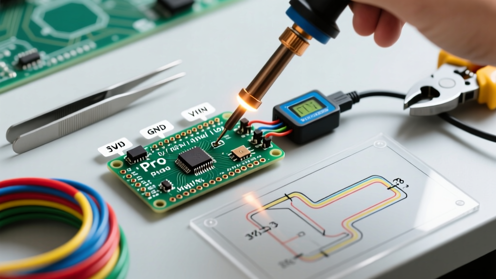
- Feed Regulated Power to VCC: Supply a clean, regulated 3.3V directly to the
VCCpin. This bypasses the MIC5219 LDO completely. - Sever the LED Trace: Use an X-Acto knife to carefully cut the copper trace connecting the onboard power LED. As documented in Nick Gammon's authoritative guide on Arduino power saving, removing the LED and bypassing the regulator can drop the ATmega328P's
power_downsleep current to roughly 120nA (0.00012mA). - Remove the Regulator (Advanced): For extreme weight and space optimization in 2026 wearable tech, desoldering the MIC5219 chip entirely prevents any reverse-leakage currents when the board is powered via VCC.
2026 Sensor Compatibility & I2C Pull-Up Workflows
Modern environmental sensors like the Sensirion SCD41 (CO2) or Bosch BME680 (Air Quality) rely heavily on I2C. A frequent workflow stall occurs when a sensor fails to initialize on the Pro Mini's A4/A5 pins.
Unlike the Arduino Nano or Uno, the standard SparkFun Pro Mini (DEV-11113) and its high-quality clones do not include onboard I2C pull-up resistors. If your breakout board also lacks them (common with ultra-low-power raw sensor dies), the I2C bus will float, resulting in Wire.endTransmission() errors or complete bus lockups.
The Fix: Solder a 4.7kΩ resistor array between VCC and the A4/A5 pins directly on your perfboard layout. Do not rely on the ATmega328P's internal pull-ups (INPUT_PULLUP), as their resistance (typically 30kΩ-50kΩ) is too weak to maintain the fast rise times required by modern 400kHz Fast-Mode I2C sensors.
Common Pinout Pitfalls That Derail Timelines
Even experienced makers fall victim to the hardware quirks of the ATmega328P's physical pin mapping. Avoid these specific edge cases to keep your project on schedule:
The A6 and A7 Digital I/O Illusion
Pins A6 and A7 are physically located next to the other analog pins, but internally, they are only connected to the ADC (Analog-to-Digital Converter) multiplexer. They lack digital input buffers and output latches.
Failure Mode: Attempting to use digitalWrite(A6, HIGH) or pinMode(A7, INPUT_PULLUP) will silently fail.
Workflow Rule: Reserve A6 and A7 strictly for reading analog voltages, such as battery dividers or photoresistors. If you need digital I/O or internal pull-ups, you must use A0-A5.
The Pin 13 LED Bootloader Flash
Pin 13 is tied to an onboard status LED. During the bootloader sequence (the first 1-2 seconds after reset or power-on), this pin will toggle rapidly. If you have a relay, MOSFET, or sensitive enable pin wired to D13, your peripheral will flicker or trigger unpredictably on every wake-up cycle. Route critical actuators to D4-D9 instead.
Conclusion: Designing for the Next Iteration
Mastering the pro mini arduino pinout is about more than just knowing which wire goes where; it is about anticipating the electrical realities of the ATmega328P. By standardizing your FTDI auto-reset harness, intentionally routing power through VCC for low-quiescent sleep states, and respecting the analog-only limitations of A6/A7, you transform the Pro Mini from a frustrating legacy board into a highly predictable, ultra-efficient node. Implement these workflow optimizations in your next breadboard layout, and you will spend less time chasing serial errors and more time analyzing field data.