
Why Every Maker Must Understand the Arduino Input Pullup
When designing digital input circuits for microcontrollers, the Arduino input pullup is arguably the most vital, yet frequently misunderstood, configuration tool in your arsenal. Whether you are building a simple mechanical keyboard with an ATmega328P or designing a complex IoT control panel with an ESP32-S3, reading the state of a switch or button reliably is paramount. In this comprehensive guide, we will dissect the electrical engineering principles behind internal pull-up resistors, provide a bulletproof wiring schematic, and explore advanced edge cases that destroy beginner projects.
The Physics of Floating Pins and CMOS Impedance
Before writing a single line of code, you must understand the enemy: the floating pin. Modern microcontrollers utilize CMOS (Complementary Metal-Oxide-Semiconductor) logic for their GPIO (General Purpose Input/Output) pins. When a pin is configured as an input and left unconnected, its internal impedance is astronomically high—often exceeding 100 Megohms.
Because of this extreme high-impedance state, the pin acts as a microscopic antenna. It absorbs electromagnetic interference (EMI) from nearby AC wiring, switching power supplies, and even the static charge from your body. The result is a rapidly oscillating logic state that bounces randomly between HIGH and LOW. This phenomenon causes ghost inputs, erratic serial monitor spam, and unintended actuations in robotics. To anchor the pin to a known voltage state when the switch is open, we use a pull-up resistor.
Internal vs. External Pull-Up Resistors: A Technical Matrix
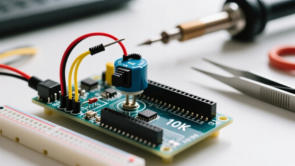
Historically, makers soldered external 10kΩ resistors to the breadboard to pull the pin up to VCC (5V or 3.3V). Today, silicon manufacturers integrate these resistors directly into the silicon die. Below is a technical comparison of internal versus external pull-up implementations across popular maker platforms.
| Platform / MCU | Internal Pull-Up Value | External Resistor Recommended | Current Draw (Approx @ VCC) |
|---|---|---|---|
| Arduino Uno (ATmega328P) | ~30kΩ (20kΩ - 50kΩ range) | 10kΩ | 166 µA (Internal) / 500 µA (External) |
| ESP32 / ESP32-S3 | ~45kΩ | 10kΩ - 4.7kΩ | 74 µA (Internal) |
| Raspberry Pi Pico (RP2040) | ~50kΩ to 80kΩ | 10kΩ | 60 µA (Internal) |
| Arduino Due (SAM3X8E) | Not universally available | 10kΩ Mandatory | N/A |
As documented in the official Arduino pinMode() reference, invoking the internal resistor saves board space, reduces BOM (Bill of Materials) costs, and minimizes solder joint failures. However, the higher resistance of internal pull-ups (30kΩ+) makes them slightly more susceptible to high-frequency EMI in noisy industrial environments compared to a stiff 4.7kΩ external resistor.
Step-by-Step: Wiring a Button Using INPUT_PULLUP
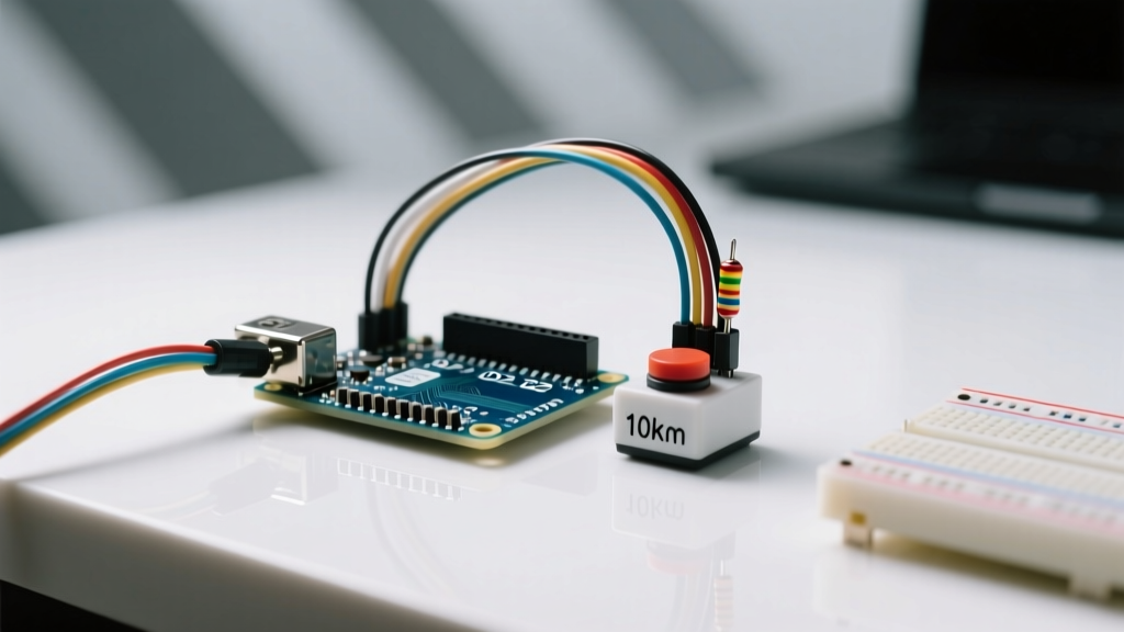
The beauty of the internal pull-up is the drastic simplification of your hardware layout. You no longer need to route VCC to every switch. Follow these exact steps for a fail-safe connection:
- Identify the Switch Terminals: Use a multimeter in continuity mode to find the two pins of your momentary tactile switch that are normally open (NO).
- Connect to Ground: Run a jumper wire from one NO terminal directly to the microcontroller's
GNDpin. - Connect to GPIO: Run a second jumper wire from the other NO terminal to your chosen digital input pin (e.g., Digital Pin 2).
- Verify Isolation: Ensure no stray wire strands are bridging the GND and GPIO lines, which would bypass the switch entirely.
Pro-Tip: If you are wiring a matrix keypad (like a 4x4 membrane), the internal pull-ups are usually sufficient for the column lines, but you may need external diodes (1N4148) to prevent ghosting when multiple keys are pressed simultaneously.
Coding the Arduino Input Pullup: The Inverted Logic Paradigm
When you activate the internal pull-up, the pin rests at HIGH (VCC). When you press the button, you are physically connecting the pin to GND. Therefore, the logic is inverted: LOW means pressed, HIGH means released. This trips up many beginners transitioning from external pull-down circuits.
Below is the production-ready C++ sketch to implement this. It includes serial feedback and a basic timing delay to mitigate switch bounce.
const int BUTTON_PIN = 2;
const int LED_PIN = 13;
int buttonState = 0;
int lastButtonState = HIGH;
unsigned long lastDebounceTime = 0;
unsigned long debounceDelay = 50; // 50ms debounce window

void setup() {
  pinMode(LED_PIN, OUTPUT);
  // CRITICAL: Activate the internal pull-up resistor
  pinMode(BUTTON_PIN, INPUT_PULLUP);
  Serial.begin(115200);
}

void loop() {
  int reading = digitalRead(BUTTON_PIN);

  // Software debouncing logic
  if (reading != lastButtonState) {
    lastDebounceTime = millis();
  }

  if ((millis() - lastDebounceTime) > debounceDelay) {
    if (reading != buttonState) {
      buttonState = reading;
      // Remember: LOW means the button is physically pressed
      if (buttonState == LOW) {
        digitalWrite(LED_PIN, HIGH);
        Serial.println("Action Triggered: Button PRESSED");
      } else {
        digitalWrite(LED_PIN, LOW);
      }
    }
  }
  lastButtonState = reading;
}
For a deeper dive into why mechanical contacts bounce and how to handle it at the hardware level using RC networks, consult SparkFun's comprehensive guide on pull-up resistors and switch debouncing.
Long Wire Runs: The Hidden Enemy of Internal Pull-Ups
Internal pull-up resistors are incredibly convenient, but their relatively high resistance (typically 30kΩ to 50kΩ) introduces a hidden vulnerability: parasitic capacitance. When you run a long wire from a microcontroller to a remote button—such as in a home automation wall switch or an automotive dashboard—the wire acts as a capacitor.
The combination of the internal pull-up resistor (R) and the wire's parasitic capacitance (C) forms an unintentional RC low-pass filter. The time constant (τ = R × C) dictates how fast the pin can transition from LOW back to HIGH when the button is released. If you are using a 50kΩ internal pull-up and a 3-meter cable with 100pF of capacitance, the rise time might be sluggish. In high-speed polling scenarios or interrupt-driven architectures, this slow rise time can cause the microcontroller to miss rapid button presses or trigger multiple interrupts due to lingering in the undefined logic threshold region (between 0.3 VCC and 0.7 VCC).
The Solution: For wire runs exceeding 1 meter, disable the internal pull-up and solder an external 4.7kΩ or 10kΩ resistor directly at the microcontroller pin. This 'stiffens' the pull-up, drastically reducing the RC time constant and ensuring sharp, clean logic transitions.
Hardware Debouncing: When Software Isn't Enough
While the software debounce delay (e.g., 50ms) in our code example is sufficient for simple UI buttons, industrial environments and high-precision rotary encoders require hardware debouncing. Mechanical contacts physically bounce upon impact, creating microsecond voltage spikes that can overwhelm software polling loops.
To implement a hardware debounce circuit alongside your Arduino input pullup configuration, you can add a simple RC (Resistor-Capacitor) filter. However, since we are utilizing the internal pull-up, we only need to add a capacitor. Solder a 100nF (0.1µF) ceramic capacitor directly across the switch terminals (between the GPIO pin and GND).
When the button is pressed, the capacitor discharges instantly through the switch to GND (pulling the pin LOW). When released, the internal 30kΩ pull-up resistor slowly charges the 100nF capacitor. This creates a smooth, exponential voltage curve that completely absorbs the mechanical bounce, delivering a pristine digital signal to the microcontroller's Schmitt trigger input.
Critical Edge Cases: ESP32 Bootstrapping and Short Circuit Traps
While the ATmega328P is forgiving, modern 3.3V microcontrollers like the ESP32 introduce severe hardware edge cases that can brick your device or prevent it from booting.
1. The ESP32 Bootstrapping Pin Hazard
The ESP32 uses specific GPIO pins to determine its boot mode upon power-up. If you wire a button with an internal pull-up to these pins, you may inadvertently force the chip into UART download mode or cause a boot-loop.
- GPIO 0: Must be HIGH to boot from flash. If a button pulls it LOW on startup, the ESP32 enters serial bootloader.
- GPIO 2: Must be LOW or floating to boot. An internal pull-up here can sometimes interfere with SDIO boot modes.
- GPIO 12 (MTDI): Determines the flash voltage (1.8V vs 3.3V). Pulling this up incorrectly can cause the internal voltage regulator to mismatch the SPI flash chip, leading to immediate brownouts.
Always consult the Espressif ESP-IDF GPIO API Reference before assigning input pull-ups on system-critical pins.
2. The OUTPUT HIGH Short Circuit Trap
A catastrophic failure mode occurs when a developer mistakenly configures a pin as OUTPUT and writes it HIGH, intending to use it as a makeshift pull-up. If the user then presses the button (which is wired to GND), they create a dead short from VCC to GND through the microcontroller's internal silicon trace. This bypasses the resistor entirely, drawing hundreds of milliamps instantly, and will permanently destroy the GPIO pin or the entire MCU die. Always use INPUT_PULLUP, never OUTPUT.
Summary and Best Practices
Mastering the Arduino input pullup configuration is a rite of passage for embedded systems engineers. By leveraging internal silicon resistors, you streamline your PCB layout, reduce component count, and write cleaner firmware. Remember to respect the inverted logic paradigm, implement software debouncing to filter mechanical contact chatter, and rigorously verify bootstrapping requirements when migrating from 5V AVR architectures to 3.3V ARM or Xtensa platforms.