
The Architecture: Brain Meets Muscle
Integrating a Raspberry Pi with an Arduino is a foundational architecture in advanced maker projects. The Raspberry Pi (running Linux) acts as the high-level brain, handling network requests, computer vision, and database logging. The Arduino acts as the real-time muscle, managing PWM motor control, analog sensor polling, and hardware interrupts. However, bridging the gap between a 3.3V Linux SoC and a 5V microcontroller requires precise configuration to avoid catastrophic hardware failure.
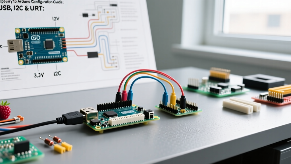
This guide details the three primary communication protocols for establishing a raspberry to arduino link: USB Serial, I2C, and hardware UART. We will cover exact wiring, logic level translation, and Linux-side daemon configurations.
The Voltage Divide: Why 3.3V Meets 5V
The most common point of failure when connecting these boards is ignoring logic level thresholds. The Raspberry Pi 4 and 5 utilize Broadcom SoCs (BCM2711 and BCM2712) whose GPIO pins are strictly limited to 3.3V. Applying 5V to a Pi GPIO pin will permanently destroy the SoC pad. Conversely, classic 5V Arduinos (like the Uno R3 or Nano V3) require a minimum of 3.0V to reliably read a HIGH signal, meaning the Pi's 3.3V output is usually sufficient for the Arduino's RX/SDA lines, but the Arduino's 5V TX/SCL lines must be stepped down.
Critical Warning: Never connect a 5V Arduino I2C or UART TX pin directly to a Raspberry Pi GPIO pin. Always use a bidirectional logic level converter or a precision voltage divider. For a deep dive on signal translation, refer to the Adafruit Level Shifter Guide.
Hardware Bill of Materials (BOM)
| Component | Model / Spec | Approx. Cost (2026) | Purpose |
|---|---|---|---|
| Host Computer | Raspberry Pi 5 (4GB) | $60.00 | Linux Host / Brain |
| Microcontroller | Arduino Nano V3 (ATmega328P) | $14.00 | Real-time I/O / Muscle |
| Level Shifter | BSS138 Bidirectional (4-channel) | $2.50 | Safe 3.3V to 5V I2C/UART |
| Resistors | 1kΩ and 2kΩ (1/4W) | $0.10 | UART Voltage Divider |
| Wiring | 22 AWG Silicone Jumper Wires | $5.00 | Low-resistance connections |
Method 1: USB Serial Configuration (The Plug-and-Play Route)
USB is the safest and fastest method to configure a raspberry to arduino link, as the physical connection handles the 5V-to-3.3V serial conversion via the Arduino's onboard USB-to-Serial chip (usually a CH340 or ATmega16U2).
Step-by-Step USB Setup
- Physical Connection: Connect the Arduino Nano to the Pi via a high-quality USB-A to Mini-USB cable. Avoid unshielded cables longer than 1 meter to prevent packet drops at high baud rates.
- Identify the Port: Open the Pi terminal and run
ls /dev/tty*. The Arduino will typically mount as/dev/ttyUSB0(CH340 chip) or/dev/ttyACM0(ATmega16U2 chip). - Verify the Link: Install the serial monitor tool:
sudo apt install minicom. Runminicom -D /dev/ttyUSB0 -b 115200. Reset the Arduino; you should see the bootloader output.
Persistent USB Naming via udev Rules
A major edge case in USB configuration is port reassignment. If you reboot the Pi, /dev/ttyUSB0 might become /dev/ttyUSB1. To fix this, create a persistent symlink using udev rules.
Run lsusb -v | grep -i serial to find the Arduino's serial number. Then create a rule file:
sudo nano /etc/udev/rules.d/99-arduino.rules
Add the following line (replace the ID and serial with your specific hardware):
SUBSYSTEM=="tty", ATTRS{idVendor}=="1a86", ATTRS{idProduct}=="7523", ATTRS{serial}=="YOUR_SERIAL", SYMLINK+="arduino_nano"
Reload rules with sudo udevadm control --reload-rules && sudo udevadm trigger. Your Arduino will now reliably appear at /dev/arduino_nano.
Method 2: I2C Bus Integration (For Sensor Sharing)
I2C is ideal when the Pi needs to poll the Arduino for aggregated sensor data without tying up a hardware UART port. However, I2C requires careful attention to pull-up resistors. The Raspberry Pi has onboard 1.8kΩ pull-up resistors tied to 3.3V on GPIO 2 (SDA) and GPIO 3 (SCL). The Arduino has no default pull-ups, but if you add 5V pull-ups to the Arduino side, you will back-feed 5V into the Pi's 3.3V rail. The BSS138 level shifter isolates these buses perfectly.
I2C Wiring Matrix
| Raspberry Pi 5 Pin | BSS138 Level Shifter | Arduino Nano Pin |
|---|---|---|
| Pin 1 (3.3V Power) | LV (Low Voltage) | - |
| Pin 2 (5V Power) | HV (High Voltage) | 5V Pin |
| Pin 6 (GND) | GND (Both sides) | GND |
| GPIO 2 (SDA1) | LV1 | - |
| - | HV1 | A4 (SDA) |
| GPIO 3 (SCL1) | LV2 | - |
| - | HV2 | A5 (SCL) |
Software Configuration
Enable I2C on the Pi using the configuration tool: sudo raspi-config -> Interface Options -> I2C -> Enable. Install the tools: sudo apt install i2c-tools python3-smbus2.
Verify the connection by running i2cdetect -y 1. If wired correctly, you will see the Arduino's address (e.g., 0x08) in the grid. For comprehensive pinout references and I2C bus mappings, consult the definitive Raspberry Pi Pinout Database.
On the Arduino side, use the Wire library to configure the device as a slave:
Wire.begin(8); // Join I2C bus with address 0x08
Wire.onRequest(requestEvent);
Method 3: UART Hardware Serial (Low-Latency Command)
UART provides the lowest latency and most robust framing for continuous byte streams, such as sending real-time PID motor commands. The challenge here is twofold: Linux serial console conflicts and voltage translation.
Disabling the Linux Serial Console
By default, the Raspberry Pi routes the Linux boot console and login shell to the primary UART (/dev/serial0). If left enabled, the Pi will send garbage boot text to the Arduino, and the Arduino's replies will trigger Linux login prompts.
- Run
sudo raspi-config. - Navigate to Interface Options -> Serial Port.
- When asked "Would you like a login shell to be accessible over serial?", select No.
- When asked "Would you like the serial port hardware to be enabled?", select Yes.
- Reboot the Pi.
The Voltage Divider Circuit
Because UART TX/RX lines are unidirectional, we only need to step down the Arduino's 5V TX to the Pi's 3.3V RX. A simple resistor voltage divider is cheaper and highly effective for baud rates under 250,000.
- Arduino TX (D1) connects to a 2kΩ resistor.
- The other end of the 2kΩ resistor connects to Pi GPIO 15 (RXD).
- A 1kΩ resistor connects from Pi GPIO 15 (RXD) to GND.
- Arduino RX (D0) connects directly to Pi GPIO 14 (TXD) (The Pi's 3.3V is safely above the Arduino's 3.0V HIGH threshold).
This divider mathematically drops the 5V signal: 5V * (1k / (2k + 1k)) = 1.66V drop, leaving exactly 3.33V at the Pi's RX pin. For more on AVR serial thresholds, review the Arduino Communication Protocols Documentation.
Failure Modes and Troubleshooting Matrix
When configuring a raspberry to arduino bridge, edge cases frequently arise. Use this diagnostic matrix to resolve common roadblocks.
| Symptom | Probable Cause | Actionable Fix |
|---|---|---|
Permission denied on /dev/ttyUSB0 | User lacks dialout group permissions. | Run sudo usermod -a -G dialout $USER and reboot. |
I2C i2cdetect shows all addresses (00-77) | SDA/SCL shorted to GND or missing pull-ups on the HV side. | Check BSS138 HV power rail. Ensure 5V is reaching the shifter. |
| UART receives random garbage characters | Baud rate mismatch or serial console still active. | Verify cmdline.txt lacks console=serial0,115200. Match baud rates exactly. |
| Pi reboots when Arduino is plugged in via USB | Arduino is drawing >1.2A, tripping the Pi's USB overcurrent protection. | Power the Arduino via its Vin pin with an external 7-12V supply; share GND. |
Final Configuration Advice
For production deployments, avoid relying on USB serial due to the mechanical fragility of Mini-USB connectors and the overhead of the CH340 driver. Hardwire the UART or I2C connections using JST-PH connectors and implement a software heartbeat. If the Pi fails to receive a heartbeat packet from the Arduino over I2C every 500ms, trigger a watchdog reset via a dedicated GPIO pin tied to the Arduino's RESET line. This ensures your combined system remains resilient in unattended, remote environments.