
The Arduino Giga R1 WiFi: A New Architecture in a Classic Footprint
At approximately $95 USD, the Arduino Giga R1 WiFi represents a massive leap in microcontroller computing power. Built around the STMicroelectronics STM32H747XI dual-core processor (a 480 MHz Cortex-M7 and a 240 MHz Cortex-M4), it packs the performance of a high-end embedded Linux SBC into a board that physically mirrors the legendary Arduino Mega2560. However, this physical similarity is a trap for the unprepared maker. As of 2026, the transition to advanced ARM architectures means legacy compatibility is no longer guaranteed simply by plugging a shield into the headers. This guide provides a deep-dive technical analysis of Arduino Giga shield compatibility, peripheral integration, and the electrical realities of migrating from 8-bit AVR to 32-bit ARM ecosystems.
The 3.3V Logic Paradigm Shift
The most critical compatibility hurdle for the Giga R1 is its strict 3.3V logic level. The STM32H747XI GPIO pins have an absolute maximum voltage rating of 3.6V. Feeding a 5V signal from a legacy Mega shield—such as an older I2C sensor module or a 5V SPI display—will permanently destroy the silicon on the M7 core.
According to SparkFun's guide on logic levels, mixing 5V and 3.3V systems requires careful attention to both voltage thresholds and current backfeed. While some 3.3V microcontrollers are '5V tolerant' on specific pins, the Giga's high-speed communication buses (SPI, I2C, FMC) are not. You must audit every shield for 5V output signals before connecting them to the Giga.
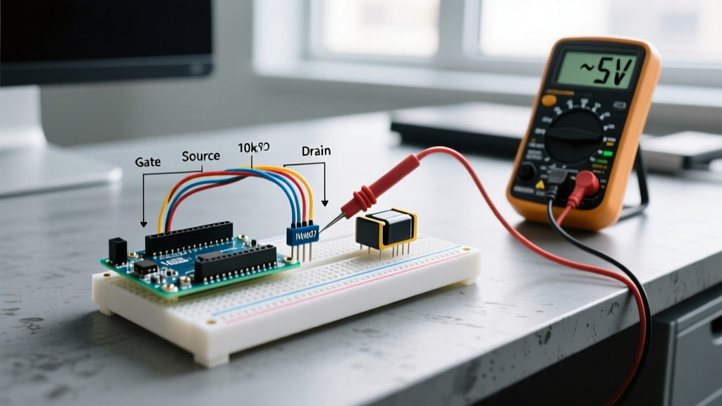
Critical Warning: Never backfeed 5V into the Giga's 3.3V I/O pins, even through pull-up resistors on I2C lines. If a shield has 4.7kΩ pull-ups tied to 5V on the SDA/SCL lines, you must physically cut those traces and reroute them to the 3.3V rail, or use an I2C level shifter like the PCA9306.
Form Factor vs. Pin Mapping: The Mega Illusion
While the Giga shares the Mega2560 mounting holes and header spacing, the internal pin routing is fundamentally different. The Mega2560 relied on the ATmega2560's specific port mappings, which placed the SPI bus on digital pins 50-53. The Giga does not route its primary SPI bus to these pins. Instead, it relies on the standard 6-pin ICSP header and specific alternate function pins.
SPI and I2C Header Nuances
| Protocol | Mega2560 Pinout | Giga R1 Pinout | Compatibility Impact |
|---|---|---|---|
| SPI (MOSI) | Pin 51 | ICSP Header / Pin 11 (Alt) | Shields hardcoding Pin 51 will fail to communicate. |
| SPI (MISO) | Pin 50 | ICSP Header / Pin 12 (Alt) | Requires software remapping or jumper wires. |
| SPI (SCK) | Pin 52 | ICSP Header / Pin 13 (Alt) | Standard ICSP shields work; pin-based shields fail. |
| I2C (SDA) | Pin 20 | Pin 20 / Dedicated Header | Directly compatible on standard I2C headers. |
| I2C (SCL) | Pin 21 | Pin 21 / Dedicated Header | Directly compatible on standard I2C headers. |
For a comprehensive map of the board's alternate functions, always refer to the official Arduino Giga R1 WiFi documentation, which details the STM32 pin multiplexing matrix.
Shield Compatibility Matrix
Below is a practical compatibility matrix for popular Arduino shields when paired with the Giga R1 in 2026.
| Shield / Module | Logic Level | Physical Fit | Compatibility Status & Required Modifications |
|---|---|---|---|
| Arduino Motor Shield Rev3 | 5V Tolerant Inputs | Perfect | Works. The L298P H-bridge accepts 3.3V logic triggers from the Giga without issue. No mods needed. |
| Adafruit 2.8" TFT Shield (SPI) | 3.3V / 5V | Perfect | Partial. If using the ICSP header for SPI, it works. If the library hardcodes Mega pins 50-53, you must modify the library to use Giga's SPI1 or software SPI. |
| Seeed Studio CAN-BUS Shield | 5V (MCP2515) | Perfect | Fails without mods. Requires a 4-channel logic level shifter (e.g., TXB0108) on the SPI lines to step down 5V MISO to 3.3V. |
| Standard SSD1306 I2C OLED | 3.3V - 5V | Wiring Required | Works perfectly. Modern SSD1306 modules have onboard regulators and accept 3.3V I2C logic natively. |
| Arduino Ethernet Shield 2 | 3.3V / 5V | Perfect | Works. The W5500 chip operates natively at 3.3V and communicates via the ICSP header. |
Power Delivery and Thermal Limits
The Giga R1 WiFi introduces USB-C Power Delivery (PD) negotiation, a massive upgrade over the legacy USB-B barrel jack paradigm. However, power routing requires careful planning to avoid thermal throttling or brownouts.
- USB-C Input: The board can negotiate up to 3A at 5V if connected to a compatible PD wall brick. This provides roughly 15W of total system power, ideal for driving high-current LED matrices or multiple servos via the 5V rail.
- VIN Pin (7V - 12V Recommended): The Giga utilizes an AP63203 buck converter to step down VIN to 5V. While the chip is rated for 2A continuous output, the PCB's thermal dissipation limits practical continuous draw to about 800mA if your input voltage is at the higher end (e.g., 18V-24V). If you need to draw 1.5A+ continuously from the 5V pin, power the board via USB-C PD, not the VIN pin.
- 3.3V Rail Limits: The onboard 3.3V LDO can supply up to 800mA. This is usually sufficient for the STM32H747XI, external QSPI flash, and a few sensors, but powering high-draw 3.3V cellular modules (like the SIM7600) directly from the Giga's 3.3V pin will cause immediate voltage sag and MCU resets.
Advanced Peripheral Buses: FMC and QSPI
Where the Giga truly separates itself from the Mega is in its external memory interfaces. The STM32H747XI architecture exposes the Flexible Memory Controller (FMC) and Quad-SPI (QSPI) buses. While no legacy Mega shield utilizes these, custom PCBs designed for the Giga can interface directly with external SDRAM chips (like the IS42S16160J) for high-speed audio buffering or framebuffers for large TFT displays. When designing custom shields for the Giga, routing these high-speed traces requires strict impedance matching (typically 50Ω single-ended and 90Ω differential) to prevent signal integrity failures at 480 MHz clock speeds.
Software Workarounds for Hardcoded Pins
If you are migrating a legacy codebase that hardcodes Mega-specific pins for SPI or UART, the 2026 Arduino core for the Giga provides software remapping functions. Instead of physically rewiring your shield with jumper cables, you can redefine the SPI bus in your setup() loop:
#include <SPI.h>

void setup() {
  // Remap SPI to alternate pins if your shield uses non-ICSP routing
  SPI.setMISO(PIN_12);
  SPI.setMOSI(PIN_11);
  SPI.setSCK(PIN_13);
  SPI.begin();
}
This leverages the STM32's internal pin multiplexing matrix, allowing the hardware SPI peripheral to route signals to different physical GPIO pads without falling back to slow software-emulated SPI.
Level Shifting Strategies for Legacy 5V Hardware
When you absolutely must interface a 5V peripheral (like a legacy TTL serial GPS module or a 5V parallel LCD), bidirectional level shifting is mandatory. Avoid using simple resistor voltage dividers for high-speed buses like SPI or I2C; the parasitic capacitance will round off the square waves, causing data corruption at speeds above 1 MHz. Instead, use active MOSFET-based shifters like the BSS138 or dedicated ICs like the Texas Instruments TXB0108. The TXB0108 auto-direction sensing is ideal for SPI MISO/MOSI lines, ensuring seamless 3.3V to 5V translation with propagation delays under 10ns.
Troubleshooting Common Giga Boot and Upload Failures
Because the Giga relies on a complex dual-core architecture and a native USB stack, upload failures are a common rite of passage. If the Arduino IDE fails to recognize the board, or the upload stalls at 0%, follow these specific edge-case troubleshooting steps:
- The Double-Tap Reset: Unlike the ATmega chips that auto-reset via the DTR line, the STM32 bootloader sometimes hangs if the user code crashes the USB stack immediately upon boot. Quickly double-tapping the red RESET button forces the Giga into the STM32 DFU/Bootloader mode, exposing a stable port for the IDE to flash new firmware.
- USB-C Cable Data Verification: A surprising number of USB-C cables bundled with modern consumer electronics are 'charge-only' and lack the D+/D- data lines. Always verify your cable supports data transfer.
- USB Hub Power Starvation: If connected through an unpowered USB 3.0 hub, the Giga's initial PD negotiation may fail, causing the board to brownout during the flash erase cycle. Connect directly to a motherboard rear I/O port or a powered PD hub.
By respecting the 3.3V logic boundaries, understanding the SPI routing differences, and properly managing power delivery, the Arduino Giga R1 WiFi becomes an incredibly robust platform capable of bridging the gap between simple microcontrollers and full-scale embedded Linux systems.