
The Core Technology: Biometric Sensing Modalities
Integrating a finger scanner into an Arduino project elevates a standard maker build into a secure, biometric-controlled system. However, treating a fingerprint sensor as a simple digital button is a fundamental misunderstanding of the technology. To successfully architect a biometric access control system, lockbox, or personalized environment, you must understand the underlying physics of the sensor, the data pipeline it utilizes, and the strict electrical requirements for microcontroller interfacing.
Modern biometric sensors generally fall into three distinct hardware categories, each with unique failure modes and environmental tolerances:
1. Optical Sensors (Total Internal Reflection)
Optical sensors, such as the widely used R307 or the premium Adafruit V2 (R503), use a prism, an LED light source, and a CMOS imaging array. When a finger presses against the prism, the ridges of the fingerprint disrupt the total internal reflection of the LED light, while the valleys allow the light to reflect fully into the camera. The result is a high-contrast grayscale map of the fingerprint. Optical sensors are highly durable but can be spoofed by high-resolution 2D photographs or latent prints left on the glass surface.
2. Capacitive Sensors (Micro-Capacitor Arrays)
Capacitive sensors, like the FPC1020 modules found in many commercial smart locks, utilize an array of microscopic capacitor plates. When a finger touches the surface, the skin acts as a dielectric. The ridges of the fingerprint sit closer to the sensor plates than the valleys, creating a measurable difference in capacitance across the grid. These sensors are highly resistant to optical spoofing and perform exceptionally well in dark environments, but they struggle significantly if the user has wet fingers, as water alters the dielectric constant of the contact surface.
3. Ultrasonic Sensors
Ultrasonic scanners use high-frequency acoustic waves to map the physical 3D topology of the fingerprint, including pore depth and ridge thickness. While heavily utilized in premium smartphones (such as Qualcomm's 3D Sonic Sensor), they remain cost-prohibitive and overly complex for standard 8-bit or 32-bit Arduino hobbyist integrations in 2026.
From Ridges to Data: The Minutiae Extraction Pipeline
A common misconception among beginners is that the finger scanner stores an actual image of your fingerprint on the Arduino's EEPROM or the sensor's flash memory. In reality, storing uncompressed biometric images is computationally expensive and poses severe privacy risks. Instead, the sensor's onboard DSP (Digital Signal Processor) performs minutiae extraction.
According to the NIST Special Publication 800-76-2 regarding biometric specifications, fingerprint recognition relies on identifying specific topological anomalies, primarily:
- Ridge Endings: The exact coordinate where a friction ridge abruptly terminates.
- Bifurcations: The coordinate where a single ridge splits into two distinct paths.
- Core and Delta Points: The macro-level center and angular shifts of the fingerprint pattern.
The sensor maps the X/Y coordinates and the angular orientation of these minutiae points, generating a proprietary mathematical template (usually 256 to 512 bytes). When you enroll a finger, the Arduino commands the sensor to store this template in its internal flash library. During verification, the sensor scans the finger, generates a temporary template, and calculates a similarity score against the stored library, returning only a Pass/Fail status or an ID number to the Arduino via UART.
UART Protocol Breakdown: Speaking the Sensor's Language
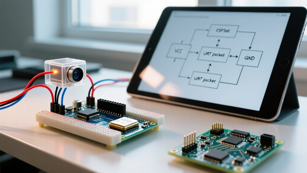
Most hobbyist finger scanner Arduino integrations rely on serial UART communication. The default baud rate for the ubiquitous R307 and Adafruit optical sensors is 57600 bps (8N1). The communication relies on a strict hexadecimal packet structure. Understanding this structure is critical for debugging when standard libraries fail.
Every command packet sent from the Arduino to the sensor follows this exact byte sequence:
| Field | Length | Description & Hex Values |
|---|---|---|
| Header | 2 Bytes | Always 0xEF01. Identifies the start of a packet. |
| Module Address | 4 Bytes | Default is 0xFFFFFFFF. Can be changed via software. |
| Package ID | 1 Byte | 0x01 (Command), 0x07 (Ack), 0x02 (Data Packet). |
| Length | 2 Bytes | Number of bytes in the Instruction + Data payload. |
| Instruction | 1 Byte | e.g., 0x03 (Fingerprint Match), 0x01 (Generate Image). |
| Checksum | 1 Byte | Sum of (Length + Instruction + Data), truncated to 8 bits. |
When utilizing libraries like the Adafruit Fingerprint library, this packet construction is abstracted. However, if you are writing bare-metal C++ for an ESP32 or ATmega328P to save memory, you must manually calculate the checksum and handle UART timeouts, which typically occur if the sensor fails to detect a finger within the hardware-defined 10-second window.
Hardware Selection Matrix (2026 Market Overview)
Selecting the correct sensor dictates your wiring topology and enclosure design. Below is a comparison of the most prevalent modules available to makers today.
| Sensor Model | Technology | Resolution (DPI) | Interface | Approx. Price (2026) |
|---|---|---|---|---|
| Generic R307 | Optical (TIR) | 500 DPI | UART / USB | $14.00 - $18.00 |
| Adafruit V2 (R503) | Optical (TIR) | 508 DPI | UART | $49.95 |
| FPC1020 Module | Capacitive | 508 DPI | UART / SPI | $22.00 - $28.00 |
Pro-Tip: The Adafruit V2 (R503) features a built-in RGB LED ring and a capacitive touch trigger, meaning the Arduino can put the sensor to sleep and wake it only upon physical contact, drastically reducing power consumption in battery-operated biometric locks.
Logic Level Translation: Preventing Silicon Damage
The most frequent cause of hardware failure in finger scanner Arduino projects is ignoring logic voltage thresholds. Most fingerprint modules operate on a 3.3V logic level for their RX and TX pins, despite accepting 3.6V to 6V on their main power (VCC) rail.
If you are using a 5V Arduino Uno or Mega, connecting the Arduino's TX pin (outputting 5V) directly to the sensor's RX pin will overvoltage the sensor's UART receiver. While some generic R307 modules might tolerate this temporarily due to internal clamping diodes, it will inevitably lead to thermal degradation and permanent silicon failure.
As detailed in SparkFun's guide on logic levels, you must step down the 5V signal to a safe 3.3V. You can achieve this using a bidirectional logic level converter (like the BSS138 MOSFET-based modules) or a simple resistor voltage divider on the Arduino TX line.
Voltage Divider Calculation
To drop 5V down to ~3.3V, use the standard voltage divider formula: V_out = V_in * (R2 / (R1 + R2)).
- R1 (Series Resistor): 2.2kΩ
- R2 (Ground Resistor): 3.3kΩ
- Result: 5V * (3300 / (2200 + 3300)) = 3.27V (Safely within the 3.3V tolerance).
Note that the sensor's TX pin (sending 3.3V to the Arduino's RX pin) does not require stepping up. The ATmega328P on the Arduino Uno recognizes any voltage above 3.0V as a logical HIGH, making the 3.3V output directly compatible with the 5V microcontroller's input.
Environmental Edge Cases and Failure Modes
Designing a robust biometric system requires anticipating real-world environmental variables. According to the Adafruit Fingerprint Sensor documentation and field testing, optical sensors suffer from specific edge cases:
- Latent Print Interference: If a user lifts their finger, the oils left on the optical prism can be read as a partial print on the next scan. Implement a software debounce in your Arduino sketch that requires the sensor's "finger detected" pin to go LOW (no finger) for at least 2 seconds before accepting a new scan.
- Ambient Light Saturation: Direct sunlight contains heavy infrared spectrums that can wash out the optical sensor's CMOS array, resulting in a blank white image. Enclosures must feature a physical shroud or lip that blocks overhead ambient light from striking the prism directly.
- Dry Skin and Calluses: Users with extremely dry skin or heavy manual calluses lack the necessary surface moisture to create a clean optical reflection or capacitive bridge. For systems deployed in harsh environments, program the Arduino to allow three consecutive failed scans before triggering an automatic lockout, and always provide a secondary override (such as an RFID backup or physical keyway).
By mastering the physical concepts, respecting the UART packet architecture, and properly managing logic voltages, your finger scanner Arduino integration will transition from a fragile prototype to a reliable, deployment-ready biometric system.