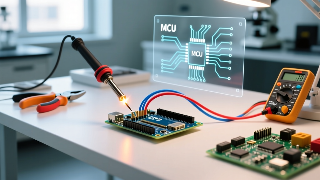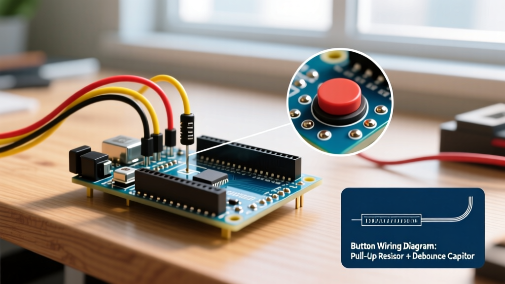

The standard Arduino reset circuit combines a 10kΩ pull-up resistor tied to VCC, a momentary pushbutton connecting the RESET pin to ground, and a 100nF series capacitor linking the serial Data Terminal Ready (DTR) line to the RESET pin. This hardware configuration forces the Microchip ATmega328P microcontroller to restart, enabling both manual intervention and automated firmware flashing. This guide is designed for embedded systems students, hardware engineers, and advanced hobbyists designing custom microcontroller boards or troubleshooting serial communication resets.
Key Term Definitions
Auto-Reset Circuit: A hardware configuration using a 100nF capacitor to couple a serial adapter's Data Terminal Ready (DTR) signal to the microcontroller's RESET pin, momentarily pulling it low to trigger the bootloader without manual button presses.
Bootloader Timeout: A predefined software window, typically 250 milliseconds on standard Arduino boards, where the microcontroller waits for incoming firmware data after a reset before executing the existing user sketch.
The Core Arduino Reset Circuit Explained
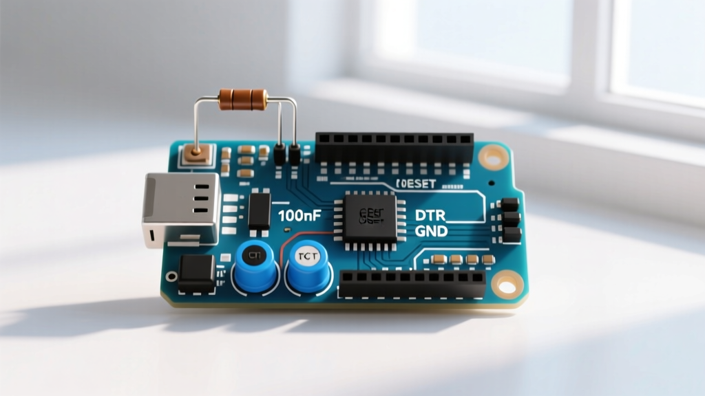
The physical reset mechanism on an Arduino Uno Rev3 relies on an active-low RESET pin. According to the Microchip ATmega328P Datasheet, the pin must be pulled below 1.5V to trigger a system reset. A 10kΩ pull-up resistor connects the RESET pin to the 5V logic rail, keeping the microcontroller in a normal running state.
Hardware Reset Button Mechanics
The manual pushbutton provides a direct, low-resistance path to ground. When pressed, it overpowers the 10kΩ pull-up resistor, instantly dropping the RESET pin voltage to 0V. Releasing the button allows the pull-up resistor to restore the pin to 5V, initiating the boot sequence. This simple RC network ensures the pin does not float and accidentally trigger resets from electromagnetic interference.
The 100nF Auto-Reset Capacitor
Automated firmware uploading requires the board to reset the moment a serial connection opens. USB-to-serial converter chips like the FTDI FT232R or CH340G toggle their DTR or Request to Send (RTS) lines when a host PC opens the COM port. A 100nF (0.1µF) capacitor sits between this serial line and the RESET pin. The sudden voltage transition on the DTR line passes through the capacitor as a brief negative spike, pulling the RESET pin low for approximately 10 milliseconds before the 10kΩ resistor charges the capacitor back to the baseline voltage.
Bootloader Logic and Reset Timing
Hardware resets only dictate the electrical state; the bootloader dictates the software response. The Optiboot bootloader resides in the dedicated boot flash section of the Microchip ATmega328P. Upon detecting a reset event, the hardware watchdog and boot fuses direct the execution pointer to the bootloader memory address.
The 250-Millisecond Bootloader Window
Once initialized, the Optiboot Bootloader Repository documentation confirms the software listens on the UART RX pin for a specific synchronization byte. It maintains this listening state for a strict 250ms timeout window. If no valid firmware handshake is detected within 250ms, the bootloader yields execution to the primary application sketch. This tight timing ensures that standard power-on events do not cause excessive boot delays.
Design Checklist for Custom Reset Circuits
When migrating from a development board to a custom printed circuit board, use this decision framework to validate your reset topology.
| Component | Standard Value | Custom Board Requirement | Failure Consequence |
|---|---|---|---|
| Pull-up Resistor | 10kΩ | Required if internal pull-up is disabled via fuses | Floating pin causes random brownout resets |
| Coupling Capacitor | 100nF | Must be placed within 5mm of the RESET pin | Parasitic trace capacitance prevents DTR spike |
| Pushbutton | Momentary SPST | Debouncing not strictly required for hardware reset | N/A |
| Capacitor to Ground | None | Do NOT add a parallel capacitor to ground | Prevents the RESET pin from rising fast enough |
Troubleshooting Common Reset Failures
If your custom board fails to accept automated uploads, the fault usually lies in the RC time constant of the auto-reset path. If the 100nF capacitor is replaced with a larger value, such as 1µF, the negative voltage spike lasts too long. The Microchip ATmega328P remains held in the reset state, preventing the bootloader from executing. Conversely, if the pull-up resistor value is too high (e.g., 100kΩ), the capacitor charges too slowly, and the reset pulse fails to reach the 1.5V threshold cleanly.
Frequently Asked Questions
Why does my Arduino reset when I open the serial monitor?
Opening the serial monitor in the Arduino IDE toggles the Data Terminal Ready (DTR) line on the USB-to-serial adapter. This transition passes through the 100nF auto-reset capacitor, pulling the RESET pin low and restarting the board. This is intentional behavior designed to prepare the bootloader for incoming code.
How does the Arduino auto-reset circuit work?
The auto-reset circuit works by AC-coupling the serial adapter's DTR or RTS control signal to the microcontroller's active-low RESET pin via a 100nF capacitor. The rapid voltage change creates a momentary negative pulse that triggers a hardware reset without requiring physical user interaction.
How to disable the Arduino auto-reset circuit?
You can disable the auto-reset feature by physically cutting the trace labeled 'RESET-EN' on the Arduino Uno Rev3 PCB, or by placing a 10µF electrolytic capacitor between the RESET pin and GND. The large capacitor absorbs the DTR spike, preventing the voltage from dropping below the 1.5V threshold.
What is the reset pin voltage threshold?
The Microchip ATmega328P requires the RESET pin voltage to drop below 1.5V (or 0.2 x VCC) to reliably trigger a hardware reset condition. The internal reset circuitry monitors this specific threshold continuously during operation.
Conclusion and Next Steps
The Arduino reset circuit elegantly bridges manual hardware control and automated serial programming through a precise 10kΩ resistor and 100nF capacitor network. Understanding this interaction between the physical RC timing and the 250ms Optiboot software window is mandatory for reliable embedded systems design. As your next step, download an open-source SPICE model of the ATmega328P reset pin and simulate the DTR capacitive discharge to verify your custom PCB trace capacitance margins before manufacturing.