
The Core Challenge: Why analogWrite() Fails
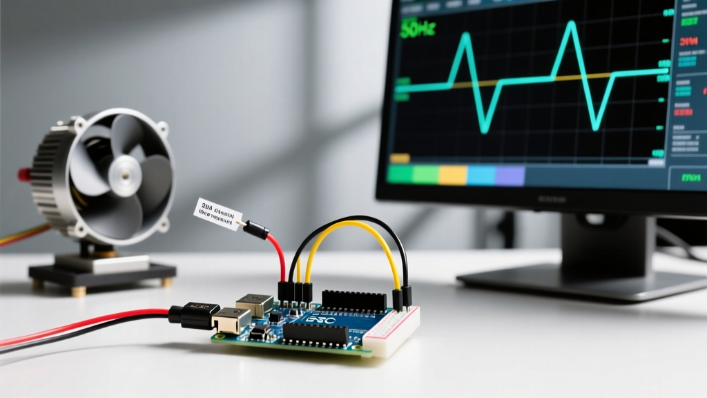
When makers first attempt to spin a brushless DC (BLDC) motor using a microcontroller, the most common mistake is treating the Electronic Speed Controller (ESC) like a standard DC motor. You cannot simply use the Arduino analogWrite() function to control an ESC. Standard Arduino PWM operates at a default frequency of roughly 490 Hz (or 980 Hz on pins 5 and 6) and maps duty cycles from 0 to 255. However, standard RC ESCs do not read duty cycles; they read precise pulse widths measured in microseconds (µs) at a much lower frequency, typically 50 Hz (a 20-millisecond period).
To successfully send a signal that the ESC recognizes, the pulse must be exactly 1000 µs for zero throttle and 2000 µs for maximum throttle, repeated every 20 ms. This is why we rely on the Arduino Servo Library, which is specifically engineered to handle the 50 Hz timer interrupts and microsecond-level precision required for RC protocols. As detailed in SparkFun's PWM Tutorial, understanding the difference between duty cycle and pulse width is the foundational step in motor control configuration.
Hardware Selection and 2026 Market Pricing
Choosing the right ESC depends on your current draw requirements and whether you need a Battery Eliminator Circuit (BEC) to power your Arduino. As of 2026, the market has stabilized, and high-quality OPTO (optically isolated, no BEC) and standard ESCs are widely available.
Recommended ESC Models for Arduino Projects
- Hobbywing Skywalker 40A (UBEC): Priced around $28-$32. Excellent for beginners because it features a robust 5V/3A BEC that can safely power an Arduino Uno or Nano without an external battery. Includes a reliable linear throttle calibration mode.
- Simonk 30A (Firmware): Often found in multipacks for $12-$15 each. Ideal for multirotor drones or lightweight rovers. Note that many Simonk ESCs are OPTO, meaning you must provide a separate 5V power source for the Arduino and the ESC signal rail.
- FLYCOLOR Raptor 390 20A: A modern 2-4S ESC ($18) that supports both standard PWM and digital protocols like DShot, making it perfect for advanced users wanting to experiment with digital telemetry.
Wiring the ESC to the Arduino
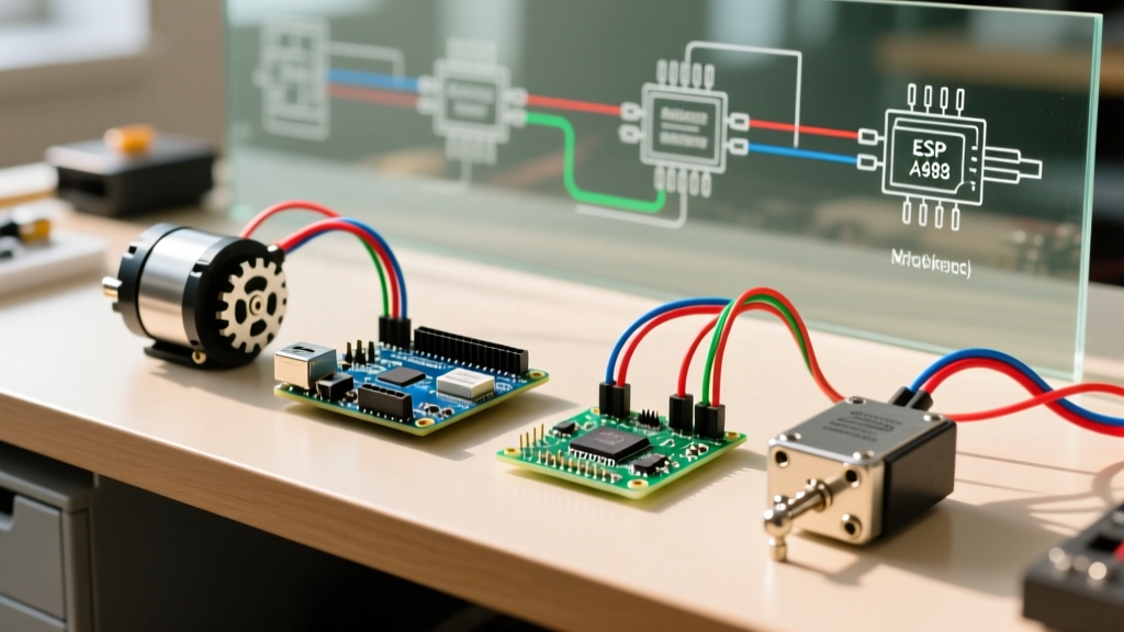
Proper wiring is critical. An ESC typically features a 3-wire servo connector (Signal, VCC, GND) and two heavy-gauge power wires (Battery Positive, Battery Negative).
CRITICAL SAFETY WARNING: Never connect the ESC's red VCC (BEC) wire to the Arduino's 5V pin while the Arduino is simultaneously plugged into your computer via USB. This creates a back-powering conflict that can fry the Arduino's onboard voltage regulator or your computer's USB port. If using the BEC, power the Arduino solely through the ESC's 5V line into the 5V pin, or use an OPTO ESC and power the Arduino via USB.
Standard Wiring Configuration (Using BEC):
- ESC Signal (White/Yellow): Connect to Arduino Pin 9 (must be a PWM-capable pin).
- ESC VCC (Red): Connect to Arduino 5V pin (if USB is disconnected).
- ESC GND (Black): Connect to Arduino GND. Never omit the ground wire; the PWM signal requires a common ground reference.
- ESC Power Wires: Connect to your LiPo battery (e.g., 3S 11.1V) via an XT60 connector. Always use a spark arrestor or series resistor when plugging in high-voltage batteries to protect the ESC capacitors.
The Mandatory Calibration Sequence
Before an ESC will accept your Arduino's throttle commands, it must learn the exact microsecond boundaries of your specific microcontroller's PWM signal. This is known as 'Throttle Calibration'. If you skip this, the ESC will interpret your zero-throttle signal as a mid-throttle command, resulting in a dangerous, immediate motor spin-up.
- Remove all propellers or mechanical loads. Safety first.
- Upload the Calibration Sketch (provided below) to your Arduino.
- Set the Serial Monitor to 115200 baud. Type '1' and press Enter to send the maximum throttle signal (2000 µs).
- Connect the LiPo battery to the ESC. You will hear a series of beeps indicating cell count, followed by a specific 'programming' beep (usually two quick beeps or a rising tone).
- Immediately type '0' in the Serial Monitor and press Enter to send the minimum throttle signal (1000 µs).
- Listen for confirmation. The ESC will emit a long beep or a musical confirmation tone. Calibration is now stored in the ESC's non-volatile memory.
Arduino Configuration Code
The following sketch handles both the calibration process and the standard arming sequence. The 'arming' sequence is a safety feature built into all modern ESCs; they require a continuous 1000 µs signal for 1 to 2 seconds upon power-up before they will spin the motor.
#include <Servo.h>

Servo esc;
int escPin = 9;

void setup() {
  Serial.begin(115200);
  esc.attach(escPin, 1000, 2000); // Define min and max pulse widths
  Serial.println("ESC Calibration & Control Sketch");
  Serial.println("Type '1' to send MAX throttle (2000us)");
  Serial.println("Type '0' to send MIN throttle (1000us)");
  Serial.println("Type 'a' to ARM the ESC");
  Serial.println("Type 's' to SPIN at 50% throttle");
}

void loop() {
  if (Serial.available()) {
    char cmd = Serial.read();
    if (cmd == '1') {
      esc.writeMicroseconds(2000);
      Serial.println("Sent: 2000us (MAX)");
    } else if (cmd == '0') {
      esc.writeMicroseconds(1000);
      Serial.println("Sent: 1000us (MIN)");
    } else if (cmd == 'a') {
      Serial.println("Arming ESC... Hold for 2 seconds.");
      esc.writeMicroseconds(1000);
      delay(2000);
      Serial.println("Armed!");
    } else if (cmd == 's') {
      esc.writeMicroseconds(1500); // 50% throttle
      Serial.println("Sent: 1500us (50%)");
    }
  }
}
Diagnostic Beep Codes and Troubleshooting
ESCs communicate errors via the motor windings acting as speakers. Understanding these beep codes is essential for debugging your configuration.
| Beep Pattern | Meaning | Resolution |
|---|---|---|
| Continuous short beeps | Throttle signal is not at zero (1000 µs) during power-on. | Ensure your Arduino code is sending 1000 µs before you plug in the battery. |
| 3 short beeps, repeating | No valid PWM signal detected on the signal wire. | Check wiring. Verify Pin 9 is attached in code. Ensure common ground is connected. |
| 2 short beeps, then pause | Low voltage cutoff triggered (Battery voltage too low). | Charge your LiPo battery or adjust the ESC's LVC settings to a lower threshold. |
| Rising musical tone | Throttle calibration successful. | Disconnect power, then reconnect to enter normal arming mode. |
Beyond PWM: DShot and Digital Protocols
While standard analog PWM is sufficient for basic rovers and simple propellers, it suffers from signal degradation, latency, and lack of telemetry. According to the comprehensive protocol breakdowns on Oscar Liang's FPV resource, modern multirotor and advanced robotics builds have largely transitioned to digital protocols like DShot (Digital Shot).
Unlike PWM, which relies on pulse width timing (and is susceptible to electrical noise), DShot sends a digital packet of 16 bits representing the throttle value, a telemetry request bit, and a CRC checksum. This eliminates the need for calibration entirely, as the ESC reads exact digital values rather than measuring analog pulse widths.
| Protocol | Signal Type | Calibration Required? | Max Refresh Rate | Best Use Case |
|---|---|---|---|---|
| Standard PWM | Analog Pulse Width | Yes | 50 - 400 Hz | Basic Arduino rovers, boats, and simple learning projects. |
| OneShot125 | Analog Pulse Width | Yes | Up to 2000 Hz | Older racing drones; faster than PWM but still analog. |
| DShot600 | Digital Packet | No | Up to 37.5 kHz | Advanced drones, precision robotics, noise-heavy environments. |
To implement DShot on an Arduino, you cannot use the standard Servo library. Instead, you must utilize hardware SPI or specialized bit-banging libraries like DShot-Arduino, which configure the microcontroller's timers to output precise digital baud rates. For 90% of general maker projects, however, mastering the 50Hz PWM calibration sequence outlined above remains the most reliable and accessible method for controlling an ESC with Arduino.