
Mastering Arduino ESC Control for Brushless Motors
Controlling high-power brushless DC (BLDC) motors is a fundamental skill in modern robotics, custom RC vehicles, and automated winch systems. While dedicated 32-bit flight controllers dominate the commercial drone space in 2026, the classic Arduino ESC control methodology remains the gold standard for bespoke maker projects. An Electronic Speed Controller (ESC) acts as the high-current bridge between your low-voltage microcontroller and the three-phase brushless motor. However, bridging the gap between a 5V logic pin and a 30A motor controller requires a strict understanding of PWM (Pulse Width Modulation) protocols, arming sequences, and power isolation.
This comprehensive guide will walk you through the exact hardware selection, wiring topology, and C++ code required to safely calibrate and drive a brushless motor using an Arduino Nano or Uno.
Hardware Requirements and Component Selection
To execute this tutorial, you need components that support standard RC PWM protocols. Avoid 'OPTO' (opto-isolated) ESCs for this specific build, as they lack an onboard BEC (Battery Eliminator Circuit) and require a separate 5V logic power supply, adding unnecessary complexity for beginners.
| Component | Recommended Model (2026) | Estimated Cost | Specification Notes |
|---|---|---|---|
| Microcontroller | Arduino Nano (ATmega328P) | $12 (Clone) / $25 (Official) | 5V logic, 16MHz clock, breadboard friendly. |
| ESC | Turnigy Plush 30A or Hobbywing Skywalker 30A | $18 - $24 | Must include 5V/2A BEC. SimonK or BLHeli firmware. |
| Brushless Motor | Emax RS2205 2300KV | $15 | 3-phase BLDC, standard bullet connectors. |
| Power Supply | ZIPP Flightmax 3S 11.1V 1300mAh LiPo | $22 | XT60 connector. Minimum 30C discharge rating. |
| Passive Components | 100µF Electrolytic Capacitor (16V+) | $0.50 | Critical for filtering PWM signal noise. |
Understanding the RC PWM Signal Protocol
Unlike standard DC motors that use varying voltage levels, Electronic Speed Controllers rely on a digital timing protocol originally designed for RC aircraft servos. The Arduino must output a 50Hz square wave (a pulse every 20 milliseconds). The width of the HIGH pulse dictates the throttle command:
- 1000µs (1ms): 0% Throttle / Minimum Command
- 1500µs (1.5ms): Neutral / Stop (or 50% throttle on forward-only ESCs)
- 2000µs (2ms): 100% Throttle / Maximum Command
Because the Arduino's native analogWrite() function operates at roughly 490Hz with a 0-255 duty cycle, it is entirely incompatible with ESCs. You must use the time-based Arduino Servo Library, which overrides the hardware timers to generate the precise 50Hz microsecond pulses required by the ESC's microcontroller.
Wiring Topology and the BEC Danger Zone
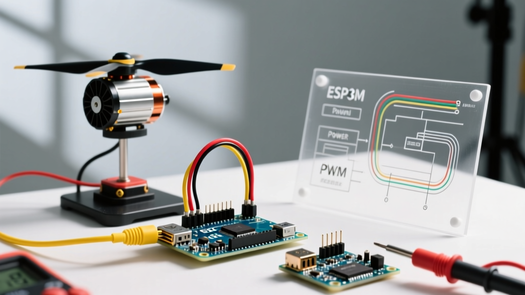
Proper wiring is where most makers destroy their hardware. The ESC harness typically features three thick phase wires (Blue, Yellow, Red/Orange) and a ribbon cable containing Signal, 5V, and Ground.
CRITICAL HARDWARE WARNING: Never connect your Arduino to a PC via USB while the ESC's BEC is feeding 5V into the Arduino's 5V pin. This creates a backfeed voltage conflict that will fry the Arduino's linear regulator or USB-to-Serial interface chip. Always unplug the USB before applying LiPo power, or physically cut/remove the 5V BEC wire and rely solely on USB power during bench testing.
Standard Bench Wiring (Using BEC Power)
- Phase Wires: Connect the three ESC phase wires to the three motor wires. Order does not matter initially; if the motor spins backward, simply swap any two wires.
- Signal Wire (White/Yellow): Connect to Arduino Digital Pin 9 (D9).
- Ground Wire (Black): Connect to Arduino GND. Common ground is mandatory for signal reference.
- 5V Wire (Red): Connect to Arduino 5V pin (Ensure USB is unplugged).
- Power: Connect the LiPo battery to the ESC's XT60 connector.
Step 1: The Calibration and Arming Sketch
Before an ESC will accept variable throttle commands, it must be 'armed'. Most ESCs require a specific sequence: they must see a 1000µs (zero throttle) signal upon power-up to confirm the operator's safety intent. Furthermore, you must calibrate the ESC to your specific Arduino's pulse boundaries.
Upload the following calibration sketch. Once uploaded, plug in your LiPo battery. The ESC will play a startup tone, followed by a specific arming beep sequence.
#include <Servo.h>

Servo esc;
const int escPin = 9;

void setup() {
  Serial.begin(9600);

  // Attach ESC to pin, explicitly defining min and max pulse widths
  esc.attach(escPin, 1000, 2000);

  Serial.println('Sending minimum throttle (1000us) to arm...');
  esc.writeMicroseconds(1000);

  // Wait for ESC to recognize the signal and arm (usually 2-3 seconds)
  delay(3000);
  Serial.println('ESC should be armed. Listen for the confirmation beep.');
}

void loop() {
  // Keep sending the idle signal to prevent ESC timeout
  esc.writeMicroseconds(1000);
  delay(20);
}
Step 2: Continuous Throttle Control
Once you have verified the arming sequence (indicated by a solid tone or a specific multi-beep pattern depending on the firmware), you can implement variable control. The following sketch ramps the motor up and down, simulating a soft-start mechanism which prevents sudden current spikes that could trigger the ESC's low-voltage cutoff (LVC).
#include <Servo.h>

Servo esc;
const int escPin = 9;

void setup() {
  esc.attach(escPin, 1000, 2000);

  // Arming Sequence
  esc.writeMicroseconds(1000);
  delay(3000);
}

void loop() {
  // Ramp up from 1100us to 1600us (approx 10% to 60% throttle)
  for (int pulse = 1100; pulse <= 1600; pulse += 10) {
    esc.writeMicroseconds(pulse);
    delay(50); // Soft start ramp delay
  }

  // Hold at 60% throttle for 3 seconds
  delay(3000);

  // Ramp down safely
  for (int pulse = 1600; pulse >= 1000; pulse -= 10) {
    esc.writeMicroseconds(pulse);
    delay(50);
  }

  // Idle for 2 seconds before repeating
  delay(2000);
}
Troubleshooting Common Failure Modes
Working with high-current inductive loads introduces electrical noise and edge cases that standard Arduino PWM tutorials rarely address. Use this diagnostic matrix to resolve common issues:
| Symptom | Root Cause | Engineering Solution |
|---|---|---|
| ESC beeps continuously, refuses to arm. | Arduino is not sending a clean 1000µs signal on boot, or the ESC's throttle range is uncalibrated. | Verify esc.attach() bounds. Manually calibrate by sending 2000µs, plugging in power, waiting for special beeps, then sending 1000µs. |
| Motor twitches or jitters at idle. | High-frequency noise from the BEC or servo rail corrupting the PWM timer. | Solder a 100µF electrolytic capacitor directly across the 5V and GND pins on the Arduino header to stabilize logic voltage. |
| Motor cuts out under heavy load. | Battery voltage sag triggering the ESC's Low Voltage Cutoff (LVC). | Disable LVC via ESC programming card, or upgrade to a LiPo with a higher 'C' rating and larger mAh capacity. |
| Arduino resets when motor spins up. | Brownout condition caused by massive current draw pulling the BEC voltage below 4.5V. | Isolate the Arduino power. Use a dedicated 5V UBEC (Universal BEC) or power the Arduino via USB/external buck converter, tying only GND and Signal to the ESC. |
Beyond PWM: The Shift to Digital Protocols
While analog PWM remains the most accessible method for Arduino ESC control, it is susceptible to signal degradation over long wires and requires manual calibration. In advanced 2026 robotics applications, makers are increasingly adopting digital protocols like DShot (Digital Shot). DShot sends binary packets (16 bits per frame) over the signal wire, completely eliminating the need for throttle calibration and providing immunity to electrical jitter. While native DShot libraries for 8-bit AVR Arduinos are limited by hardware timer constraints, upgrading to a 32-bit Arduino Portenta or Teensy 4.1 allows for bit-banged DShot600, offering telemetry feedback and bidirectional control natively. For standard prototyping and heavy-duty winch systems, however, the Servo library PWM method detailed above remains the most robust and universally compatible approach.