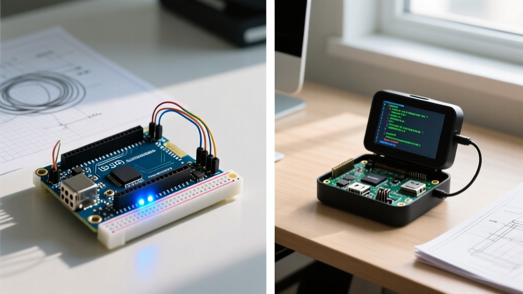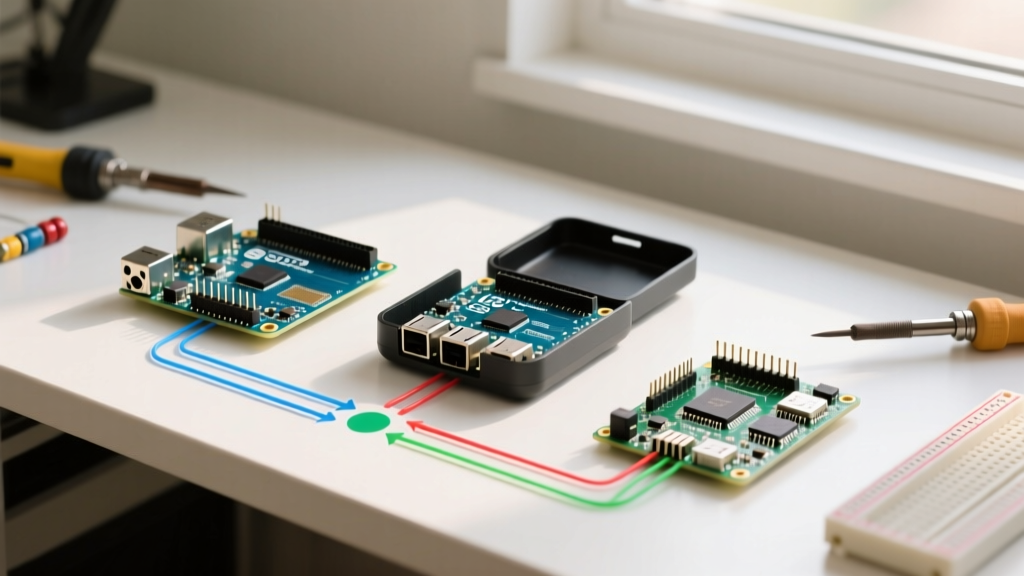

The Embedded Triad: Defining the Configuration Landscape
When embedded engineers and advanced makers evaluate hardware for a new project, the 'Arduino vs Raspberry Pi vs ESP32' debate is inevitable. While hobbyist forums often reduce this comparison to simple processing power or price tags, the reality of deploying a reliable system hinges entirely on configuration overhead, toolchain maturity, and peripheral management. In 2026, the lines between microcontrollers (MCUs) and single-board computers (SBCs) have blurred, but their underlying configuration architectures remain fundamentally distinct.
This guide bypasses superficial spec-sheet comparisons and dives deep into the actual configuration workflows, boot processes, and edge-case failure modes of the Arduino ecosystem (focusing on the UNO R4 and Nano ESP32), the Raspberry Pi 5 / Zero 2 W, and standalone Espressif ESP32-S3 modules.
Toolchain Architecture: IDE vs OS vs RTOS
The most immediate divergence in the Arduino vs Raspberry Pi vs ESP32 comparison is how you configure the hardware environment before writing a single line of application logic.
Arduino: The Abstraction Layer
Arduino IDE 2.3 abstracts hardware configuration into hidden text files. When you select a board, the IDE parses boards.txt and platform.txt to pass specific compiler flags (like -DF_CPU=16000000L) to the GCC toolchain. While this lowers the barrier to entry, it obscures clock tree configurations and memory partitioning. To modify the Arduino Nano ESP32's partition table (e.g., allocating more flash for OTA updates), you must manually edit the partitions.csv file buried in the local Arduino15 packages directory, a process that frequently breaks when the IDE updates its core packages.
Raspberry Pi: The Linux Device Tree
Configuring a Raspberry Pi 5 running Debian Bookworm means interacting with the Linux kernel's Device Tree. Hardware configuration is primarily handled via the /boot/firmware/config.txt file. According to the Raspberry Pi Configuration Documentation, enabling specific hardware interfaces requires injecting Device Tree Overlays (.dtbo files). For example, enabling an external RTC module requires adding dtparam=i2c_vc=on and dtoverlay=i2c-rtc,ds3231. This provides immense flexibility but requires a working knowledge of Linux kernel modules and I2C addressing.
ESP32-S3: The Kconfig Menu
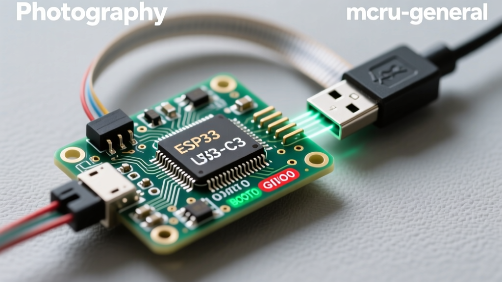
Standalone ESP32 development via ESP-IDF v5.3 relies on Kconfig, a menu-driven configuration system inherited from the Linux kernel. By running idf.py menuconfig, engineers configure everything from the FreeRTOS tick rate (default 1000Hz) to the exact SPI RAM clock speed. The ESP-IDF Kconfig Documentation details how these choices compile into a binary sdkconfig file. This offers granular, deterministic control over the MCU's behavior, making it the superior choice for strict real-time applications.
Peripheral Configuration: I2C, SPI, and UART
Configuring communication buses reveals the starkest differences in hardware abstraction. Below is a comparison matrix of how each platform handles I2C bus initialization and pull-up resistor management.
| Feature | Arduino (UNO R4 WiFi) | Raspberry Pi 5 | ESP32-S3 (ESP-IDF) |
|---|---|---|---|
| I2C Initialization | Wire.begin(SDA, SCL); (Software defined) |
dtparam=i2c_arm=on in config.txt (Hardware fixed) |
i2c_master_bus_config_t struct (Hardware flexible) |
| Internal Pull-ups | Weak internal (~20kΩ), requires external 4.7kΩ | Fixed 1.8kΩ hardware pull-ups on GPIO 2/3 | Configurable via software (up to 45kΩ), external recommended |
| Clock Stretching | Handled by Renesas RA4M1 I2C peripheral | Known BCM2712 hardware bug; requires software workaround | Native hardware support with adjustable timeout limits |
| Max Bus Speed | 1 MHz (Fast Mode Plus) | 400 kHz (Fast Mode) | 1 MHz (Fast Mode Plus) / 3.4 MHz (High Speed) |
Expert Insight: A common failure mode when migrating from Arduino to Raspberry Pi involves I2C sensor timeouts. The Raspberry Pi's fixed 1.8kΩ pull-ups on the primary I2C bus can cause signal integrity issues if you are multiplexing multiple sensors or routing traces longer than 10cm. In contrast, the ESP32-S3 allows you to map the I2C peripheral to almost any GPIO pin via the GPIO matrix, providing superior PCB routing flexibility.
Network Provisioning and Wireless Setup
Wireless configuration is where the SBC vs MCU divide becomes most apparent.
- Raspberry Pi (NetworkManager): As of the Bookworm release, Raspberry Pi OS has deprecated
wpa_supplicantin favor of NetworkManager. Configuring Wi-Fi now requires using thenmclicommand-line tool or thenmtuiinterface. While robust for enterprise WPA3-Enterprise networks, this adds significant boot-time overhead (often 3-5 seconds just to initialize the network stack). - ESP32-S3 (Provisioning): The ESP-IDF provides the
wifi_provisioningcomponent, allowing engineers to configure Wi-Fi credentials over BLE or SoftAP using a standardized mobile app protocol. This is critical for commercial IoT deployments where hardcoding SSIDs in the Arduino IDE 2.x Documentation sketches is a security vulnerability. - Arduino (WiFiNINA / WiFiS3): The Arduino UNO R4 WiFi utilizes the
WiFiS3library. Configuration is strictly imperative:WiFi.begin(ssid, pass). It lacks native support for complex enterprise authentication (like 802.1X EAP-TLS) without writing custom AT-command passthroughs to the ESP32-S3 coprocessor.
Power Management and Boot Optimization
If your project is battery-powered, the configuration required to achieve low-power states will dictate your hardware choice.
The Boot-Time Reality Check: A Raspberry Pi Zero 2 W takes approximately 12 to 18 seconds to boot to a state where a Python script can read a GPIO pin. An ESP32-S3 boots from deep sleep to executing user code in under 15 milliseconds. Arduino boards utilizing a traditional bootloader (like the UNO R3) introduce a 2-second serial enumeration delay, though the R4 Minima bypasses this via native USB CDC.
Configuring Deep Sleep on ESP32-S3
To achieve the advertised ~7µA deep sleep current on an ESP32-S3, configuration goes far beyond calling esp_deep_sleep_start(). You must:
1. Isolate power domains using esp_sleep_pd_config(ESP_PD_DOMAIN_RTC_PERIPH, ESP_PD_OPTION_OFF).
2. Disable all LDOs not tied to the RTC memory.
3. Ensure all GPIO pins are configured as analog inputs (rtc_gpio_isolate()) to prevent leakage current through internal pull-ups.
Failure to configure the RTC GPIO isolation is the number one reason makers report 2mA+ sleep currents instead of microamps.
Raspberry Pi Power Gating
The Raspberry Pi 5 cannot truly 'sleep' in the MCU sense. The lowest power state is a halt state initiated via sudo halt, which drops power consumption to roughly 1.2W (idle) down to ~0.8W, but requires a physical toggle of the power button or an external watchdog MCU on the I2C bus to wake it. For battery applications requiring wake-on-interrupt, the Pi is fundamentally unsuited without an external power-gating load switch (like a TI TPS2553) controlled by a secondary low-power MCU.
Real-World Failure Modes and Edge Cases
Understanding how these platforms fail in production separates prototyping from engineering.
1. The ESP32 ADC Non-Linearity Trap
The ESP32's internal SAR ADC is notoriously non-linear, particularly near the 0V and 3.3V rails. If your configuration requires precise analog voltage reading (e.g., a battery fuel gauge), you must configure the ADC attenuation to 11dB and apply Espressif's factory-stored eFuse calibration data via esp_adc_cal_characterize(). Arduino wrappers often ignore this calibration, leading to 10-15% measurement errors.
2. Raspberry Pi SD Card Corruption
In industrial environments with frequent power loss, configuring a Raspberry Pi with a standard ext4 root filesystem guarantees eventual SD card corruption. The required configuration fix involves moving the root filesystem to an NVMe drive via the Pi 5's PCIe 2.0 HAT, or configuring the OS as a read-only overlayfs using raspi-config > Performance Options > Overlay File System.
3. Arduino Memory Fragmentation
When configuring Arduino sketches that heavily use the String class for JSON parsing (e.g., via ArduinoJson), the Renesas RA4M1's 32KB SRAM quickly suffers from heap fragmentation. Unlike the ESP-IDF, which offers sophisticated heap capabilities and memory tracing via heap_caps_get_free_size(), the Arduino environment requires manual implementation of static memory pools to prevent random std::bad_alloc crashes after days of uptime.
Final Decision Matrix
Use this framework to finalize your hardware selection based on your configuration constraints:
| Project Requirement | Recommended Platform | Why? |
|---|---|---|
| Battery-powered IoT sensor (Coin cell) | ESP32-S3 | Microamp deep sleep, native BLE/Wi-Fi provisioning, flexible GPIO matrix. |
| Computer Vision / Edge AI Gateway | Raspberry Pi 5 (8GB) | Linux OS required for Docker, OpenCV, and PCIe NVMe storage configuration. |
| Legacy Industrial Shield Integration | Arduino UNO R4 WiFi | Strict adherence to the R3 mechanical footprint and 5V logic tolerance on specific GPIOs. |
| High-Speed Data Logging (SPI) | ESP32-S3 (ESP-IDF) | SPI DMA (Direct Memory Access) configuration allows background logging without CPU blocking. |
Ultimately, the choice between Arduino, Raspberry Pi, and ESP32 is not about which board is 'better,' but which configuration ecosystem aligns with your team's expertise and the physical constraints of your deployment environment. By mastering the underlying toolchains—whether that means editing Device Tree overlays, tuning Kconfig parameters, or optimizing Arduino memory allocation—you can extract maximum reliability from any of these powerful platforms.