
The Limitations of the Classic GL5528 Photoresistor
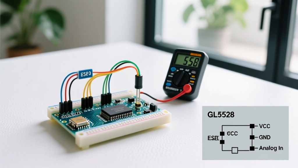
When makers first search for a photoresistor for Arduino projects, they inevitably land on the generic GL5528 cadmium sulfide (CdS) light-dependent resistor (LDR). Priced at roughly $0.15 per unit, it is the undisputed king of introductory electronics kits. However, as your projects evolve from simple night-lights to precision environmental monitoring or automated greenhouse lighting, the analog photoresistor becomes a critical bottleneck.
The GL5528 suffers from three fundamental engineering flaws:
- Non-Linear Output: The resistance-to-illuminance curve is logarithmic. A drop from 100 lux to 10 lux yields a drastically different voltage change than a drop from 1000 lux to 100 lux, making accurate lux calculations via
analogRead()nearly impossible without complex lookup tables. - Spectral Mismatch & IR Sensitivity: CdS cells are highly sensitive to infrared light. If you place a GL5528 near an incandescent bulb or an IR heat source, it will register a massive spike in 'visible' light, completely skewing your data.
- Slow Response Times: The rise and fall times for a standard CdS cell hover between 20ms and 50ms. While fine for dusk-to-dawn detection, this latency causes severe flickering and feedback loops in high-speed PWM dimming circuits.
Regulatory Note: Cadmium Sulfide (CdS) photoresistors contain heavy metals and are banned under the Restriction of Hazardous Substances (RoHS) directive in the EU. If you are migrating an Arduino prototype toward a commercial consumer product, you must replace the LDR with a RoHS-compliant silicon-based digital sensor.
Direct Comparison: CdS Photoresistor vs. Modern I2C Alternatives
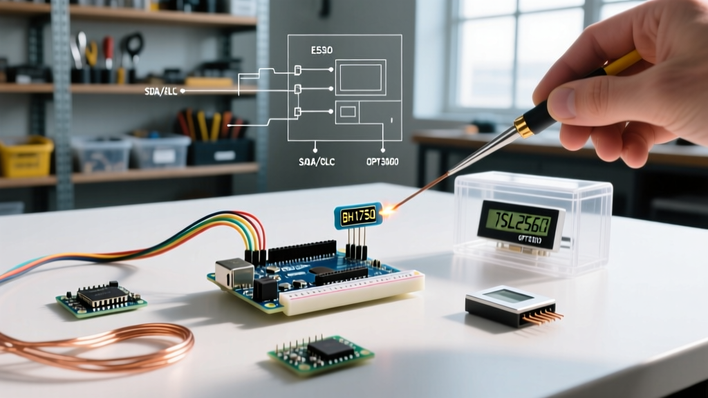
Upgrading to a digital ambient light sensor (ALS) replaces the messy analog voltage divider with a dedicated I2C integrated circuit. These chips feature onboard ADCs, automatic gain control, and human-eye spectral matching. Below is a technical comparison of the legacy LDR against the top three migration targets for 2026.
| Sensor Model | Interface | Output Type | Lux Range | Response Time | Typical Module Cost |
|---|---|---|---|---|---|
| Generic GL5528 (CdS) | Analog (Voltage Divider) | Resistance (Ω) | ~10 to 100k | 20-50ms | $0.15 |
| ROHM BH1750FVI | I2C | Direct Lux (16-bit) | 1 - 65,535 | 120ms (High Res) | $2.50 |
| ams OSRAM TSL2561 | I2C | Raw Broadband + IR | 0.1 - 40,000+ | 13.7ms - 402ms | $4.50 |
| TI OPT3001 | I2C | Direct Lux (23-bit eff.) | 0.01 - 83,000 | 100ms / 800ms | $7.00 |
Top I2C Sensor Upgrades for Your Arduino Project
Selecting the right replacement depends on your specific environmental constraints and budget. Here is a deep dive into the three most reliable migration paths.
1. ROHM BH1750FVI (The Budget-Friendly Lux Meter)
The BH1750FVI is the most common 1:1 replacement for hobbyists. It outputs a direct 16-bit lux value, entirely eliminating the need for analog mapping math. It operates at an I2C address of 0x23 (or 0x5C if the ADDR pin is pulled high). The major advantage here is simplicity: the sensor's internal spectral response is heavily tuned to match the human eye, rejecting IR interference from sunlight and heat lamps. However, its maximum lux ceiling of 65,535 means it will saturate in direct, unfiltered desert sunlight (which can exceed 100,000 lux).
2. ams OSRAM TSL2561 (The Infrared-Compensated Workhorse)
If your project operates in environments with heavy IR contamination (e.g., near grow lights or outdoor enclosures), the TSL2561 is the superior choice. Unlike the BH1750, the TSL2561 utilizes two distinct photodiodes: one broadband (visible + IR) and one IR-only. By reading both registers and performing a differential calculation, the chip mathematically strips out the IR noise to deliver a highly accurate visible lux reading. It requires slightly more complex library implementation but offers programmable integration times (13.7ms, 101ms, or 402ms), allowing you to trade response speed for extreme low-light sensitivity.
3. Texas Instruments OPT3001 (The High-Dynamic-Range Pro)
For commercial-grade migrations or scientific data logging, the Texas Instruments OPT3001 is the undisputed heavyweight. It features a 23-bit effective dynamic range via an automatic full-scale setting mechanism. This means it can accurately measure the dim glow of a standby LED (0.01 lux) and the blinding glare of direct noon sunlight (83,000 lux) without requiring manual gain adjustments. Furthermore, its built-in rejection of 50Hz and 60Hz flicker from AC-powered fluorescent lighting makes it ideal for indoor industrial automation.
Hardware Migration: Rewiring the Voltage Divider
Migrating from an analog photoresistor to an I2C sensor requires a fundamental shift in your breadboard layout. You will be completely discarding the 10kΩ pull-down resistor that formed your analog voltage divider.
Step-by-Step Rewiring Guide:
- Remove Analog Components: Disconnect the GL5528 and the 10kΩ resistor from your breadboard. Free up your
A0analog pin. - Power Routing (VCC/GND): Connect the sensor module's GND to the Arduino GND. Connect VCC to the 3.3V pin. Critical Warning: While 5V Arduinos (like the Uno R3) have 5V tolerant I2C pins, many raw BH1750 and OPT3001 silicon chips operate strictly at 3.3V. Always power the breakout board via 3.3V unless the board explicitly features an onboard LDO voltage regulator.
- I2C Data Lines (SDA/SCL):
- For Arduino Uno/Nano: Connect SDA to
A4and SCL toA5. - For Arduino Mega: Connect SDA to
20and SCL to21. - For 3.3V boards (ESP32, Arduino Due, Nano 33 IoT): Use the dedicated SDA/SCL pins mapped in the board's pinout diagram.
- For Arduino Uno/Nano: Connect SDA to
- Pull-Up Resistors: The Arduino Wire library relies on pull-up resistors for I2C communication. Most commercial breakout boards include 4.7kΩ surface-mount pull-ups onboard. If you are designing a custom PCB or wiring a raw SMD chip, you must add 4.7kΩ resistors between the SDA/SCL lines and the VCC rail.
Software Migration: Adapting Your Arduino Sketch
The software migration shifts your code from reading raw ADC values (0-1023) to requesting processed data over the I2C bus. You will replace analogRead() with the Wire.h library or a dedicated sensor abstraction layer.
Consider the following logic shift when moving to the BH1750:
Legacy Analog Logic:
int rawValue = analogRead(A0);
float voltage = rawValue * (5.0 / 1023.0);
// Complex, inaccurate math to estimate lux based on voltage divider...
Modern I2C Logic (via Adafruit_BH1750 Library):
#include <Wire.h>
#include <Adafruit_BH1750.h>

Adafruit_BH1750 bh1750;

void setup() {
  Serial.begin(115200);
  bh1750.begin(BH1750_CONTINUOUS_HIGH_RES_MODE);
}

void loop() {
  float lux = bh1750.readLightLevel();
  Serial.print('Direct Lux Reading: ');
  Serial.println(lux);
  delay(500);
}
This transition drastically reduces code bloat, eliminates floating-point mapping errors, and provides a standardized metric (lux) that can be directly fed into IoT dashboards like Home Assistant or Blynk without server-side conversion.
Real-World Failure Modes and Edge Cases
When executing this migration in the field, be aware of three common edge cases that cause I2C sensor failures:
- I2C Address Collisions: If your project already utilizes an I2C OLED display (often
0x3C) or a BME280 environmental sensor, verify your light sensor's address. The TSL2561 defaults to0x39, but can be shifted to0x29or0x49via the ADDR SEL pin if a collision occurs. - Capacitance on Long I2C Runs: I2C is designed for short, on-board traces. If you are mounting the OPT3001 at the end of a 2-meter cable inside a greenhouse, the parasitic capacitance of the wire will corrupt the I2C square waves, resulting in
NaN(Not a Number) lux readings. For runs over 30cm, switch to a specialized I2C bus extender (like the P82B715) or migrate the sensor to a local SPI interface. - Condensation and Dome Refraction: Digital sensors like the OPT3001 are highly sensitive to the optical path. If your outdoor enclosure accumates condensation on the acrylic window, the water droplets will act as micro-lenses, focusing sunlight directly onto the silicon die and causing localized saturation. Always use optically clear, anti-reflective coated glass or hydrophobic coatings over digital ALS modules.
Conclusion
Migrating away from the legacy analog photoresistor for Arduino is a mandatory step for any maker transitioning from prototype to production. By investing an extra $2.50 to $7.00 in a digital I2C sensor like the BH1750 or OPT3001, you eliminate non-linear math, bypass IR interference, and ensure your hardware complies with modern environmental standards. The initial hardware rewiring and library setup take less than an hour, but the resulting data stability will save you weeks of software troubleshooting down the line.