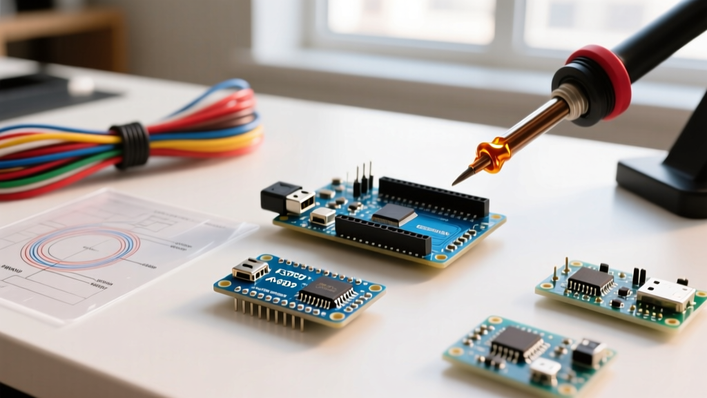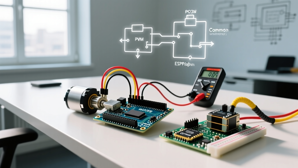

The Reality of Motor Drive Failures
When you attempt to build an Arduino control a motor system, the transition from a blinking LED to moving mechanical parts introduces a host of electrical complexities. You upload your sketch, the onboard LED blinks perfectly, but the motor merely twitches, whines, or causes the entire microcontroller to reset. This is the most common frustration in embedded prototyping.
Unlike logic-level sensors, motors are highly inductive loads that demand massive inrush currents and generate destructive voltage spikes. In 2026, while motor driver ICs have become vastly more efficient and affordable, the fundamental physics of electromagnetism remain unchanged. If your circuit is failing, it is almost always due to power starvation, grounding errors, or inductive kickback. Below is our definitive 7-step troubleshooting guide to isolate and fix your motor drive failures.
Step 1: Diagnose the 'Brownout Reset' (Power Starvation)
The number one reason an Arduino fails to drive a motor is the Brown-out Detection (BOD) mechanism. The ATmega328P (used in the Uno and Nano) has a default BOD threshold of 2.7V. If the supply voltage dips below this level for even a few microseconds, the microcontroller instantly resets to prevent memory corruption.
The Inrush Current Multiplier
A DC motor's startup (stall) current can be 5 to 10 times higher than its continuous running current. If you are attempting to power a standard 6V TT gear motor directly from the Arduino's 5V pin, the inrush current will easily exceed the 500mA absolute maximum rating of the onboard AMS1117-5.0 voltage regulator, causing a severe voltage sag.
Expert Fix: Never power motors directly from the Arduino 5V or 3.3V pins. Use a dedicated external power supply (e.g., a 12V 2A switching supply for larger motors or a 4x AA battery pack for small TT motors) and feed it into the motor driver's VCC/VM terminal.
Step 2: Establish a Common Ground Reference
Microcontrollers and motor drivers communicate via logic signals (0V to 5V). If the Arduino and the external motor power supply do not share a common ground reference, the logic signals are floating. The motor driver will interpret the Arduino's PWM or direction pins as random noise, resulting in erratic motor behavior or complete failure to start.
- Check: Ensure a physical jumper wire connects the Arduino's
GNDpin to the motor driver'sGNDterminal. - Edge Case: If using opto-isolated motor drivers (common in high-voltage industrial stepper setups), the common ground must be omitted by design, but the opto-isolator VCC must be tied to the Arduino 5V.
Step 3: Evaluate Your Motor Driver Selection
Using the wrong motor driver for your specific voltage and current requirements will lead to thermal shutdown or insufficient torque. The ancient L298N is still sold everywhere, but its bipolar transistor design causes massive voltage drops compared to modern MOSFET-based drivers.
| Driver IC | Topology | Voltage Drop | Max Continuous Current | Best Use Case | Approx. Cost |
|---|---|---|---|---|---|
| L298N | Bipolar (BJT) | ~2.0V - 3.0V | 2.0A per channel | High voltage (12V+), low efficiency | $3.00 - $5.00 |
| TB6612FNG | MOSFET | ~0.5V | 1.2A per channel | Battery-powered robots, 6V-9V motors | $4.00 - $6.00 |
| DRV8833 | MOSFET | ~0.4V | 1.5A per channel | Low voltage (2.7V-10.8V) applications | $3.50 - $5.50 |
| BTS7960 | High-Power MOSFET | ~0.1V | 43A (theoretical) | Heavy-duty actuators, e-bikes, winches | $12.00 - $18.00 |
For a comprehensive breakdown of modern driver architectures, refer to the Arduino Motor Basics documentation, which details why MOSFET drivers like the TB6612FNG are now the industry standard for low-voltage robotics.
Step 4: Suppress Inductive Kickback (Back-EMF)
When you cut power to a spinning DC motor, the collapsing magnetic field generates a reverse voltage spike (Back-EMF) that can easily exceed 50V. This spike travels back into your motor driver and can permanently destroy the H-bridge IC or reset the Arduino via ground bounce.
The Flyback Diode Requirement
While most modern ICs (like the TI DRV8833) have internal clamp diodes, they are only rated for brief transients. For heavy loads or frequent direction reversals, you must add external 1N4007 Schottky or standard rectifier diodes across the motor terminals (cathode to positive, anode to negative).
- Symptom of Failure: The motor driver gets dangerously hot to the touch within seconds, or the Arduino randomly disconnects from the USB port when the motor stops.
- Fix: Solder a 1N4007 diode directly across the motor brushes, or use a motor driver breakout board with robust external clamping capacitors (e.g., 100µF electrolytic across the main VM power rails).
Step 5: Resolve PWM Frequency and Timer Conflicts
If your motor is stuttering, emitting a high-pitched whine, or failing to respond to speed commands, you may have a software timer conflict. The Arduino Uno uses hardware timers to generate PWM signals via analogWrite(). Crucially, pins 9 and 10 are tied to Timer1.
If you are using the standard Servo.h library to control a steering servo while simultaneously trying to PWM a DC motor on pin 9 or 10, the Servo library will hijack Timer1, disabling PWM on those pins. The motor will simply run at full speed or not at all.
Expert Fix: Move your DC motor PWM input to pins 3, 5, 6, or 11, which utilize Timer2 and Timer0. For deep-dive troubleshooting on hardware timers, review the Secrets of Arduino PWM tutorial.
Step 6: Verify Logic Pin Mapping and Code Direction
A surprisingly common error in H-bridge wiring is mismatched logic pins. An H-bridge requires two digital pins per motor (IN1 and IN2) to dictate direction, and one PWM pin for speed.
The Truth Table Check
- IN1 = HIGH, IN2 = LOW: Motor spins forward.
- IN1 = LOW, IN2 = HIGH: Motor spins reverse.
- IN1 = LOW, IN2 = LOW: Motor coasts (freewheels).
- IN1 = HIGH, IN2 = HIGH: Motor brakes (shorts terminals).
If your motor is braking aggressively and drawing massive current immediately upon startup, check your code. Setting both pins HIGH creates a dynamic brake, which will trigger the driver's over-current protection (OCP) and shut down the output.
Step 7: Inspect for Mechanical Binding and Stall Conditions
Finally, do not overlook the physical hardware. If the electrical and software checks pass, the issue may be mechanical. A bound gearbox, a misaligned wheel, or an overtightened belt will cause the motor to stall. A stalled motor acts as a dead short, drawing maximum stall current continuously.
Modern drivers like the Pololu TB6612FNG breakout feature built-in thermal shutdown. If the motor stalls for more than a second or two, the IC will heat up and cut power to protect itself, making it appear as though the Arduino has stopped sending signals. Disconnect the motor from the mechanical load and test it in free-air. If it spins perfectly, your problem is mechanical binding, not electrical failure.
Summary Checklist for Motor Drive Success
- Use a dedicated external power supply capable of delivering 2x the motor's stall current.
- Always tie the Arduino GND to the Motor Driver GND.
- Upgrade from L298N to MOSFET drivers (TB6612FNG/DRV8833) for battery efficiency.
- Install flyback diodes and bulk capacitors on the power rails.
- Avoid Timer1 pins (9 & 10) when using the Servo library.
By systematically isolating power, grounding, driver topology, and software timers, you can transform a frustrating, non-responsive Arduino control a motor project into a reliable, high-torque electromechanical system.