
The Computational Reality of Sensor Fusion
When makers search for a kalman filter in arduino, they are typically met with basic 1D scalar examples designed to smooth out jitter from a single ultrasonic sensor or analog potentiometer. While these introductory sketches are useful for basic noise reduction, real-world robotics, drone stabilization, and autonomous navigation require multi-dimensional Extended Kalman Filters (EKF) or Unscented Kalman Filters (UKF) to fuse accelerometer, gyroscope, magnetometer, and GPS data.
Implementing a multi-state Kalman filter is not merely a coding challenge; it is a strict hardware compatibility issue. Matrix inversions, Jacobian calculations, and floating-point math will instantly crash underpowered microcontrollers or introduce catastrophic latency in control loops. This guide breaks down the exact MCU architectures, sensor pairings, and memory footprints required to successfully deploy Kalman algorithms in 2026.
MCU Compatibility Matrix for Kalman Implementations
The primary bottleneck for Kalman filters is not clock speed, but the presence of a hardware Floating Point Unit (FPU) and available SRAM. A standard 9-state EKF requires multiple 9x9 matrix multiplications and inversions. In single-precision C++ floats (4 bytes each), a single 9x9 matrix consumes 324 bytes of RAM. When accounting for state vectors, covariance matrices, and temporary inversion buffers, a 9-DOF EKF easily demands 2KB to 4KB of dedicated SRAM just for math operations.
| MCU Board (2026) | Core Architecture | SRAM | FPU Type | Max Kalman Complexity | Avg Price |
|---|---|---|---|---|---|
| Arduino Nano (ATmega328P) | 8-bit AVR | 2KB | None (Software) | 1D Scalar only | $22.00 |
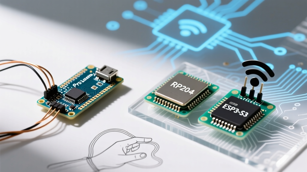
| Raspberry Pi Pico (RP2040) | Dual Cortex-M0+ | 264KB | None (Software) | Up to 6-DOF EKF (High Latency) | $4.00 |
| ESP32-S3 | Dual Xtensa LX7 | 512KB | Single-Precision | 9-DOF EKF (Real-time capable) | $8.00 |
| Teensy 4.1 | Cortex-M7 (600MHz) | 1MB | Double-Precision | 15-DOF+ UKF/EKF (Optimal) | $32.00 |
As highlighted in the official Arduino memory guide, 8-bit AVR boards simply lack the SRAM to hold the covariance matrices required for sensor fusion. Furthermore, the RP2040’s lack of a hardware FPU means that complex matrix math is handled via software emulation, introducing unacceptable latency for high-frequency IMU polling (typically 500Hz+).
Sensor Pairings: What Actually Needs an External Filter?
A common mistake in modern MCU design is applying an external Kalman filter to a sensor that already possesses an internal Sensor Hub. Understanding your sensor's internal architecture dictates your MCU compatibility requirements.
1. Sensors with Internal Sensor Fusion (No External EKF Needed)
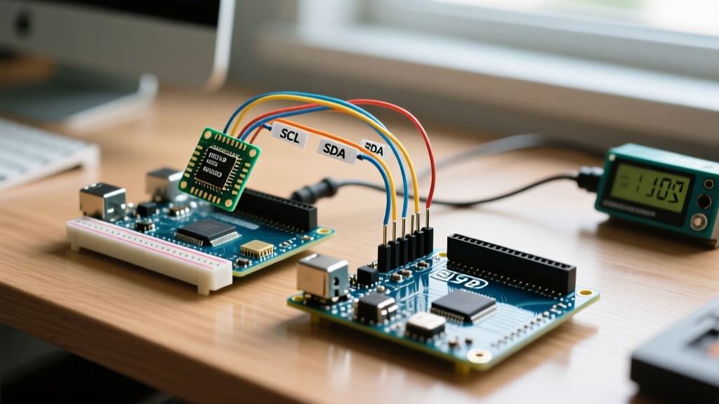
- BNO085 / BNO086 (CEVA/Hillcrest Labs): These 9-DOF IMUs feature dedicated ARM Cortex-M0+ coprocessors running proprietary Kalman algorithms internally. As noted in the Adafruit BNO085 integration guide, the host MCU only receives pre-fused quaternion data via I2C or SPI. Running an external EKF on top of this data is redundant and mathematically destructive.
- BNO055 (Bosch): An older but still prevalent chip that outputs fused Euler angles and quaternions. External filtering is only required if you are fusing this IMU with an external GPS module.
2. Raw Sensors (External EKF Mandatory)
- MPU6050 / MPU9250 / ICM-20948: These output raw, noisy accelerometer and gyroscope vectors. To achieve stable pitch/roll/yaw, your MCU must run an external EKF or complementary filter.
- BMP390 Barometer + GPS (NEO-M9N): Fusing barometric altitude with GPS Z-axis data requires a 1D or 2D Kalman filter to eliminate GPS multipath errors and barometric wind noise.
Library Memory Footprint & Selection Guide
Choosing the right library is critical for preventing stack overflows. Here is how the most popular Arduino Kalman libraries compare regarding memory and compatibility.
- SimpleKalmanFilter: Designed strictly for 1D scalar values (e.g., smoothing a LiDAR distance reading). RAM Footprint: ~60 bytes. Compatibility: All MCUs, including ATtiny85.
- Kalman.h (TKJ Electronics): A highly optimized 2D filter specifically tuned for fusing single-axis gyroscope and accelerometer data. RAM Footprint: ~300 bytes. Compatibility: ATmega328P and up.
- BasicLinearAlgebra + Custom EKF: For 9-DOF sensor fusion, developers often use matrix libraries to build custom EKFs. RAM Footprint: 2KB - 5KB depending on state vector size. Compatibility: ESP32, Teensy, STM32 only.
Edge Cases: NaN Propagation and Matrix Singularity
When deploying a kalman filter in arduino environments, the most frequent catastrophic failure mode is matrix singularity. During the covariance update step, if the determinant of the innovation covariance matrix approaches zero, the matrix inversion function will divide by zero. This generates a NaN (Not a Number).
Because Kalman filters are recursive, this NaN immediately propagates through the state vector and covariance matrix on the next loop iteration, permanently bricking the filter until the MCU is hard-reset.
The Joseph Form Solution
To prevent this on 32-bit MCUs like the ESP32, advanced implementations avoid the standard covariance update equation. Instead, they use the Joseph Form covariance update. While mathematically more verbose and slightly more CPU-intensive, the Joseph form guarantees that the covariance matrix remains symmetric and positive semi-definite, virtually eliminating NaN propagation caused by floating-point round-off errors.
Actionable Tuning Framework for Q and R Matrices
The theoretical foundation of tuning Process Noise (Q) and Measurement Noise (R) is extensively documented in resources like Kalman and Bayesian Filters in Python by Roger Labbe. However, translating this to Arduino C++ requires practical heuristics.
Tuning Measurement Noise (R)
The R matrix defines how much you trust your sensors. If R is too high, the filter ignores sensor data and relies purely on the mathematical model (causing drift). If R is too low, the filter passes raw sensor noise directly to the output.
- MPU6050 Accelerometer (Static): Start with R =
0.05. If high-frequency vibration from motors is present, increase to0.5. - NEO-M9N GPS (Horizontal Position): Dynamically scale R based on the HDOP (Horizontal Dilution of Precision) value output by the GPS module. R =
HDOP * 2.5.
Tuning Process Noise (Q)
The Q matrix defines how much you trust your system's physical model. In a drone, wind gusts and motor vibrations represent unmodeled process noise.
- Gyroscope Bias Drift: Set the Q value for gyro bias states to
0.001. This allows the filter to slowly adapt to temperature-induced gyro drift without overreacting to transient spikes. - Position/Velocity States: For ground robots, set Q to
0.1. For quadcopters experiencing rapid Z-axis acceleration, increase Q to1.5to allow the filter to track aggressive maneuvers.
Summary: Matching the Filter to the Hardware
Successfully running a Kalman filter in Arduino ecosystems requires abandoning the 'one-size-fits-all' mentality. If you are smoothing a single analog sensor, an ATmega328P with a 1D scalar filter is perfectly adequate and cost-effective. However, if your 2026 project involves 9-DOF IMU sensor fusion, GPS waypoint tracking, or autonomous navigation, you must upgrade to an ESP32-S3 or Teensy 4.1. By respecting SRAM limits, leveraging hardware FPUs, and utilizing robust mathematical forms like the Joseph update, you can achieve commercial-grade sensor fusion on hobbyist microcontrollers.