
What Does "Arduino as an ISP" Actually Mean?
In the microcontroller ecosystem, In-Circuit Serial Programming (ICSP or ISP) allows you to flash firmware directly to a target AVR chip's flash memory via the SPI protocol, bypassing the need for a pre-installed bootloader. While dedicated hardware programmers like the USBasp or Pololu AVR Programmer v2 are inexpensive (typically $6 to $15 in 2026), using a standard Arduino Uno or Nano as an ISP remains a vital skill. It serves as an emergency recovery tool for bricked chips, a cost-effective method for programming custom PCBs on the bench, and a fundamental way to understand the SPI bus architecture.
This quick reference guide cuts through the fluff, providing exact wiring matrices, critical hardware rules, and advanced avrdude troubleshooting for using the built-in ArduinoISP sketch.
Master Wiring Matrix: Programmer to Target
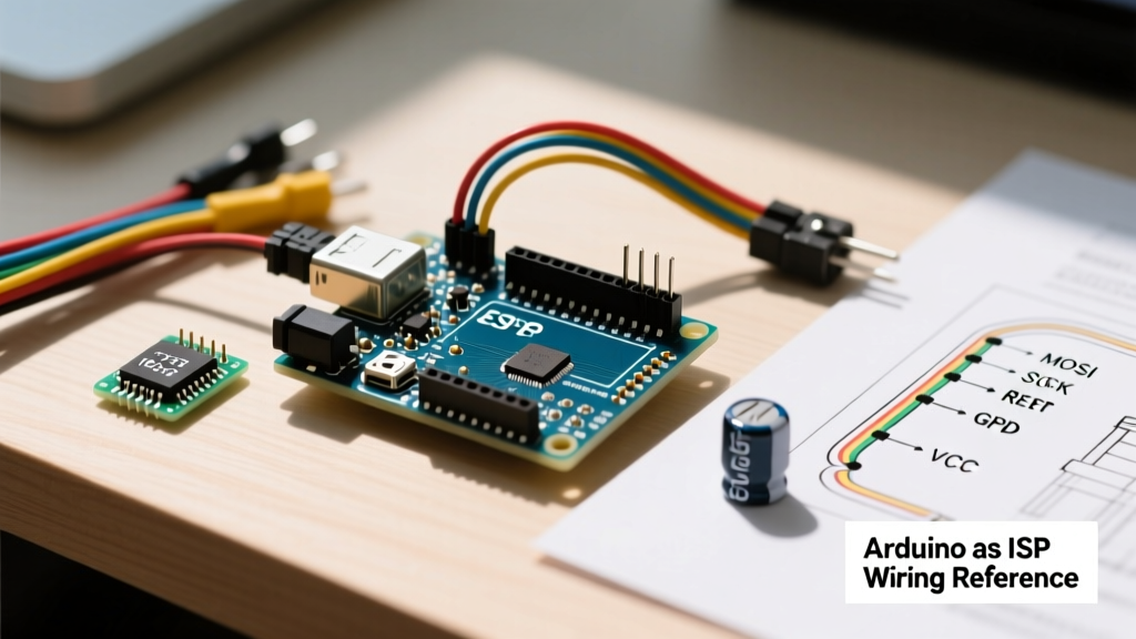
The ArduinoISP sketch utilizes the hardware SPI pins on the programmer board. Below is the definitive wiring matrix for the most common targets. Note: Always power the target board from the programmer's 5V and GND pins to ensure a shared ground reference.
| Programmer (Arduino Uno R3/R4) | Target (ATmega328P / ATtiny85) | Function / Notes |
|---|---|---|
| Pin 10 | RESET (PC6 on 328P / PB5 on t85) | Must be Pin 10 on Uno. Do not use the ICSP header reset pin. |
| Pin 11 (MOSI) | MOSI (PB3 on 328P / PB0 on t85) | Master Out, Slave In. Data flows to target. |
| Pin 12 (MISO) | MISO (PB4 on 328P / PB1 on t85) | Master In, Slave Out. Data flows from target. |
| Pin 13 (SCK) | SCK (PB5 on 328P / PB2 on t85) | Serial Clock. Synchronizes data transfer. |
| 5V | VCC | Ensure target does not exceed 5V logic tolerance. |
| GND | GND | Critical: Shared ground prevents SPI communication errors. |
The 10µF Capacitor Rule (Critical Hardware Detail)
⚠️ EXPERT WARNING: When using an Arduino Uno as an ISP programmer, you must place a 10µF electrolytic capacitor between the
RESETandGNDpins on the programmer board (striped side to GND).
Why is this necessary? When the Arduino IDE invokes avrdude to upload the sketch, it opens the serial port. On standard Arduinos, opening the serial port triggers the DTR (Data Terminal Ready) line, which pulses the RESET pin via a 0.1µF capacitor. This reboots the programmer board into its own bootloader instead of running the ArduinoISP sketch. The 10µF capacitor absorbs this DTR pulse, keeping the programmer in ISP mode. Forgetting this capacitor is the #1 cause of "programmer is not responding" errors.
Step-by-Step: Bootloader vs. Direct Upload
Understanding the difference between burning a bootloader and uploading a sketch via ISP is crucial for memory management and fuse bit configuration.
Scenario A: Burning the Bootloader
Use this when setting up a fresh ATmega328P on a breadboard or recovering a chip with corrupted fuse bits.
- Wire the programmer to the target using the matrix above.
- Upload the
ArduinoISPsketch to the programmer board. - Insert the 10µF capacitor on the programmer.
- In the IDE, select the Target Board (e.g., ATmega328P on a breadboard) and set Programmer to "Arduino as ISP".
- Click Tools > Burn Bootloader. This sets the correct fuse bits (e.g., enabling the external 16MHz crystal) and flashes the Optiboot bootloader.
Scenario B: Uploading a Sketch Directly (No Bootloader)
Use this for ATtiny85 chips or production ATmega328P deployments where you need the extra 2KB of flash memory normally reserved for the bootloader.
- Follow steps 1-4 above.
- Instead of the standard upload button, click Sketch > Upload Using Programmer (or press
Ctrl+Shift+U). - Note: This action completely overwrites and erases any existing bootloader on the target chip.
Frequently Asked Questions & Troubleshooting
FAQ 1: Why am I getting "avrdude: stk500_recv(): programmer is not responding"?
This generic avrdude error masks several distinct failure modes. Check these in order:
- Wrong COM Port: You selected the target's COM port instead of the programmer's COM port in the IDE. The IDE must communicate with the Uno running the ArduinoISP sketch.
- Missing Capacitor: The 10µF reset capacitor is missing or inserted with reverse polarity, causing the programmer to reboot into the Optiboot bootloader instead of the ISP sketch.
- Target Not Powered: The ArduinoISP sketch does not magically power a disconnected chip. Ensure 5V and GND are securely connected.
- Wiring Reversal: MOSI and MISO are swapped. Remember: Programmer MOSI connects to Target MOSI (Master Out goes to Slave In).
FAQ 2: Can I use an Arduino Nano or Mega as the ISP programmer?
Yes, but with caveats. For the Arduino Nano, the auto-reset circuit is similar to the Uno, so the 10µF capacitor trick usually works. However, some Nano clones use a different USB-to-Serial chip (like the CH340) that handles DTR differently, occasionally requiring you to physically cut the auto-reset trace on the PCB. For the Arduino Mega 2560, the hardware SPI pins are located on the ICSP header and Pins 50 (MISO), 51 (MOSI), and 52 (SCK), not pins 11-13. You must modify the ArduinoISP sketch pin definitions or wire directly to the Mega's ICSP header.
FAQ 3: My ATtiny85 sketch runs incredibly slow or serial output is garbled. Why?
This is a classic clock source mismatch. By default, a factory-fresh ATtiny85 is configured via fuse bits to use its internal 8MHz oscillator, but with the CKDIV8 fuse enabled, effectively running at 1MHz. If your code or ATTinyCore board definition expects 8MHz, the timing will be off by a factor of 8. The Fix: You must use "Arduino as ISP" to Burn Bootloader first. This doesn't actually install a bootloader on the ATtiny85; rather, it sends the avrdude commands to rewrite the fuse bits (specifically setting lfuse:w:0xe2:m), disabling CKDIV8 and enabling the full 8MHz internal clock.
FAQ 4: Can Arduino as an ISP recover a chip with completely bricked fuse bits?
No. Arduino as an ISP relies on the standard SPI protocol. If you have accidentally set the target chip's fuse bits to require an external crystal (e.g., setting the ATmega328P to "Full Swing Crystal Oscillator") and you do not have a crystal connected, the chip's internal clock will not start, and the SPI bus will remain dead. Furthermore, if you accidentally disabled the RSTDISBL (Reset Disable) fuse, the RESET pin becomes an I/O pin, permanently disabling standard ISP. In these scenarios, you need a High-Voltage Parallel Programmer (HVPP) or a High-Voltage Serial Programmer (HVSP) to force the chip into programming mode using 12V on the RESET pin. Standard Arduinos cannot output 12V natively.
Cost & Tooling Comparison: Arduino ISP vs. Dedicated Programmers (2026 Market)
When should you use an Arduino versus buying a dedicated tool? Here is a practical decision matrix based on current market pricing and use cases.
| Tool / Method | Approx. Cost | Best Use Case | Limitations |
|---|---|---|---|
| Arduino Uno as ISP | $12 (Clone) - $27 (R4) | Emergency recovery, learning SPI, bench prototyping when you already own one. | Requires 10µF cap, occupies a whole Uno, slower than native USB. |
| Generic USBasp v2.0 | $5 - $8 | High-volume flashing, permanent fixture on a maker bench. | Requires Zadig driver installation on Windows 11; lacks 3.3V logic shifting. |
| Pololu AVR Programmer v2 | $15 - $18 | Professional development, reliable cross-platform drivers, adjustable VCC. | Higher upfront cost than clones. |
| Arduino Nano (with custom shield) | $8 - $12 | Compact, portable ISP tool for field repairs. | Auto-reset circuit can be finicky without hardware modification. |
Final Expert Advice on Target Compatibility
When using the Arduino as an ISP, remember that it is strictly an AVR8 tool. It cannot program ARM Cortex-M microcontrollers (like the STM32 or SAMD21) or ESP32/ESP8266 chips, which require entirely different protocols (SWD, JTAG, or UART serial bootloaders). Furthermore, always verify your target's voltage tolerance. Programming a 3.3V ATmega328P running on a 3.3V rail with a 5V Arduino Uno's SPI lines can degrade the target's silicon over time. For 3.3V targets, use a bidirectional logic level shifter on the MOSI, MISO, SCK, and RESET lines, or switch to a 3.3V Arduino (like the Arduino Zero or a 3.3V Pro Mini) acting as the ISP programmer.
For detailed fuse bit calculations and verification before flashing, always consult the Engbedded AVR Fuse Calculator to ensure you do not accidentally lock yourself out of the microcontroller.