
The Problem with delay(): Why Hobbyist Traffic Lights Fail
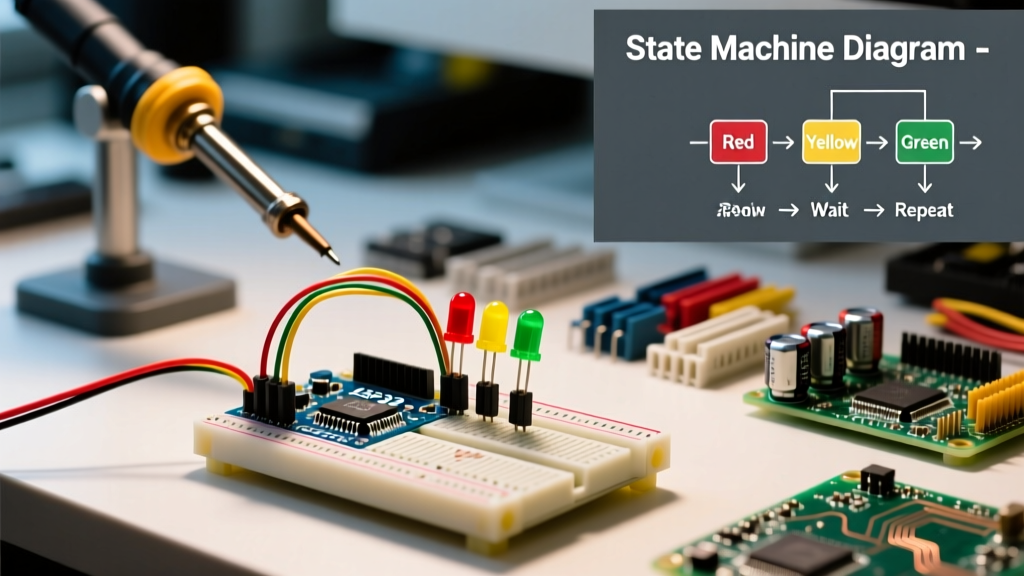
When most makers approach a traffic light Arduino project, the first instinct is to wire up three LEDs (red, yellow, green) and use the delay() function to sequence them. While this works for a static diorama, it fundamentally fails as a conceptual model for real-world embedded systems. The delay() function is blocking. When the microcontroller executes delay(5000) for a green light phase, it is entirely deaf and blind to the outside world. If a pedestrian presses a crosswalk button, or an inductive loop sensor detects an emergency vehicle during that 5-second window, the Arduino misses the input entirely until the delay finishes.
To build a robust, responsive traffic light Arduino system, we must abandon linear blocking code and adopt an event-driven architecture. This requires understanding the core concept of the Finite State Machine (FSM) and utilizing non-blocking timing functions.
Core Concept: The Finite State Machine (FSM)
A Finite State Machine is a computational model consisting of a limited number of states, transitions between those states, and triggering events. In the context of a traffic intersection, the system can only be in one specific state at any given millisecond.
Defining the States for a Single Intersection
- STATE_GREEN: Main road traffic flows. Pedestrian inputs are queued.
- STATE_YELLOW: Main road clearance. No new traffic may enter the intersection.
- STATE_ALL_RED: Critical safety buffer. Both main and cross roads are red to clear the intersection box.
- STATE_CROSS_GREEN: Cross road or pedestrian phase active.
By mapping these states to an enum in C++, the Arduino evaluates its current state on every single loop iteration (which runs thousands of times per second). It checks two things: Has the time limit for this state expired? and Has an external interrupt/event occurred? If either condition is met, it transitions to the next state.
Hardware Selection: Beyond Basic 5mm LEDs
While a breadboard with 5mm through-hole LEDs is fine for prototyping logic, a proper concept demonstrator should use hardware that mimics real-world electrical loads. In 2026, the Arduino Uno R4 Minima ($27.60) is the standard recommendation due to its 48 MHz Renesas RA4M1 ARM Cortex-M4 processor, which handles complex FSM logic and PWM dimming effortlessly. For compact, permanent installations, the Arduino Nano Every ($11.50) remains a cost-effective workhorse.
| Component | Specification / Model | Est. Price | Purpose in FSM Circuit |
|---|---|---|---|
| Microcontroller | Arduino Uno R4 Minima | $27.60 | Core logic processing and state evaluation |
| LED Modules | 12V 10mm Traffic Light Module | $14.99 (set of 3) | High-visibility visual output |
| Current Limiting | 1/4W 330Ω Carbon Film | $0.02 / ea | Protects GPIO pins if using standard 5V LEDs |
| Optocoupler | PC817 (DIP-4) | $0.15 / ea | Galvanic isolation between 5V logic and 12V loads |
| Flyback Diode | 1N4007 | $0.05 / ea | Suppresses inductive spikes from relay coils |
| Input Switch | Momentary Pushbutton (12mm) | $0.40 | Pedestrian crosswalk request trigger |
Implementing Non-Blocking Logic with millis()
To replace delay(), we use the millis() function, which returns the number of milliseconds since the Arduino began running the current program. According to the official Arduino millis() reference, this function rolls over after approximately 49 days. Proper FSM design accounts for this rollover by using subtraction rather than addition in time comparisons: if (currentMillis - previousMillis >= interval).
This non-blocking approach allows the loop() function to continuously poll the pedestrian button. If the button is pressed during STATE_GREEN, the system simply sets a boolean flag (pedestrianRequest = true). When the minimum green time expires, the FSM checks this flag and transitions to STATE_YELLOW instead of looping back to green.
Real-World Timing: FHWA and NEMA Standards
A true concept explainer must bridge the gap between hobbyist code and professional civil engineering standards. In the United States, traffic signal timing is governed by guidelines from the Federal Highway Administration (FHWA) and hardware standards from the National Electrical Manufacturers Association (NEMA). The FHWA Traffic Signal Timing Manual outlines strict safety parameters that your Arduino FSM must respect.
The Yellow and All-Red Clearance Intervals
You cannot arbitrarily assign 2 seconds to a yellow light. The FHWA mandates that the yellow change interval must typically fall between 3.0 and 5.0 seconds, calculated based on the 85th-percentile speed of approaching traffic. Furthermore, an All-Red clearance interval of 1.0 to 2.0 seconds is required to ensure vehicles that entered the intersection on yellow have time to clear the conflict area before cross-traffic receives a green signal.
Professional controllers adhere to the NEMA TS2 standard, which includes a "Conflict Monitor Unit" (CMU). The CMU is a hardware watchdog that instantly flashes all lights to red if it detects a fault (e.g., conflicting green lights). In an advanced Arduino project, you can simulate a CMU by reading back the voltage at the LED output pins via analog inputs; if the FSM commands RED but the analog pin reads 5V on the GREEN line, the system triggers a fail-safe interrupt.
Edge Cases: Switch Bounce and Pedestrian Interrupts
Mechanical pushbuttons suffer from "contact bounce." When a pedestrian presses the crosswalk button, the metal contacts physically bounce against each other for a few milliseconds, registering as dozens of rapid presses. If your FSM relies on hardware interrupts (attachInterrupt()) to catch the button press, switch bounce can cause the interrupt service routine (ISR) to fire multiple times, potentially corrupting state variables.
Expert Tip: Never rely solely on software debouncing for critical safety inputs. Implement hardware debouncing by placing a 100nF ceramic capacitor in parallel with the pedestrian pushbutton, combined with a 10kΩ pull-up resistor. This creates an RC low-pass filter that smooths the voltage spike, delivering a clean, single falling edge to the Arduino GPIO pin.
Scaling to High Voltage: Opto-Isolation
Driving real 12V or 120V traffic light fixtures directly from an Arduino's 5V logic pins will instantly destroy the microcontroller. You must use opto-isolation. The PC817 optocoupler uses an internal infrared LED and a phototransistor to pass the signal across an optical gap. The Arduino powers the IR LED (via a 220Ω resistor), while a separate 12V power supply drives the high-power traffic light LEDs through the phototransistor and a MOSFET (like the IRLZ44N). This ensures that a catastrophic short circuit on the 12V street side cannot send high voltage back into your Arduino's delicate 32-bit ARM core.
Frequently Asked Questions (FAQ)
Can I use an Arduino for a real street intersection?
No. While the FSM logic concepts are identical, real-world intersections require NEMA-certified controllers (like the Econolite EOS or Siemens M60) that feature ruggedized watchdog timers, conflict monitors, and environmental hardening that a standard development board lacks.
How do I handle power outages in my Arduino traffic light model?
Implement a supercapacitor (e.g., 5.5V 10F) across the power rails paired with a voltage monitoring IC. When the main power drops, the Arduino detects the voltage sag via an analog pin, immediately transitions the FSM to an ALL_RED or FLASH_RED state, and writes the current state to the EEPROM before the supercapacitor drains completely.
What is the best way to simulate inductive loop sensors?
For a tabletop model, use Hall effect sensors (like the A3144) paired with small neodymium magnets embedded in the underside of your model cars. This accurately simulates the non-contact magnetic detection used in real-world asphalt loop detectors.