
The Anatomy of an OBDII Arduino Connection
Integrating an Arduino with a vehicle's On-Board Diagnostics (OBD-II) port opens the door to custom digital dashboards, telemetry loggers, and head-up displays (HUDs). Mandated for all US vehicles since 1996 and European petrol cars since 2001, the OBD-II Data Link Connector (DLC) provides a standardized gateway into the vehicle's internal networks. However, bridging the gap between a 5V (or 3.3V) microcontroller and a 12V automotive environment requires a firm grasp of physical layer transceivers and protocol decoding.
When approaching an OBDII Arduino project, makers generally choose between two distinct hardware architectures: the UART-based ELM327 interpreter, or the raw SPI-based CAN bus transceiver (like the MCP2515). Understanding the trade-offs between these two methods is critical for project success, especially as modern 2025 and 2026 vehicle architectures increasingly segment infotainment, powertrain, and diagnostic networks.
Hardware Comparison: ELM327 vs. Raw CAN Bus
Before writing a single line of code, you must select the physical interface. The ELM327 datasheet outlines a command-based AT interpreter, while raw CAN modules speak directly in hexadecimal bus frames.
| Feature | ELM327 (UART / Bluetooth) | MCP2515 + TJA1050 (Raw CAN) |
|---|---|---|
| Cost | $10 - $18 (Clone adapters) | $4 - $8 (Standalone module) |
| Interface | UART (Serial) / AT Commands | SPI (Requires 5 logic pins) |
| Latency | High (50ms - 200ms per PID) | Ultra-Low (< 2ms per frame) |
| Protocol Handling | Automatic (Handles ISO9141, KWP, CAN) | Manual (Must configure CAN ID & masking) |
| Best Use Case | Basic OBD2 Scanners, Bluetooth Dashboards | High-speed telemetry, custom CAN injection, HUDs |
Deep Dive: Wiring the MCP2515 to the OBD-II Port
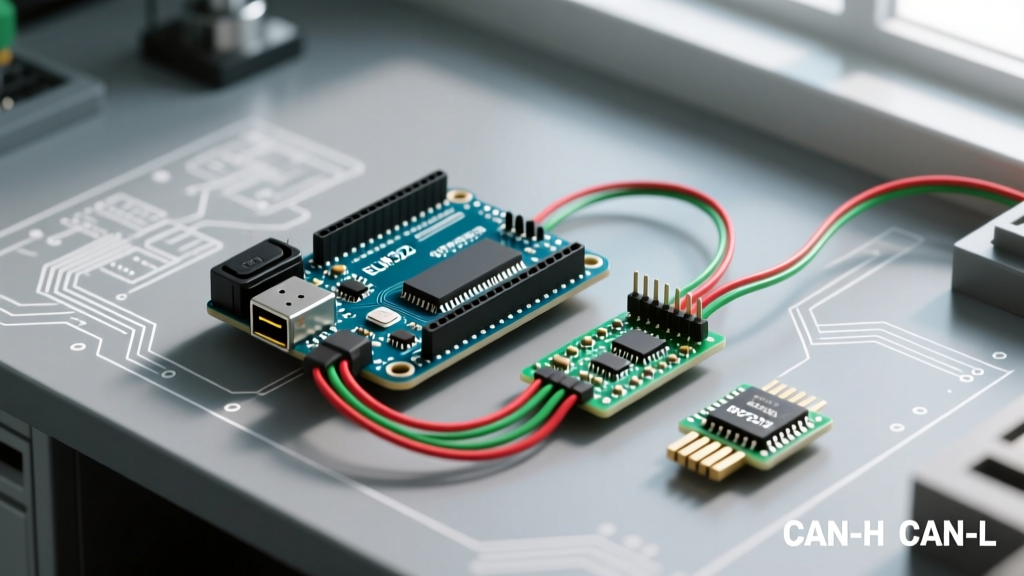
For high-performance applications like real-time shifting indicators or lap timers, the MCP2515 CAN controller paired with a TJA1050 transceiver is the gold standard for 5V Arduino boards (Uno, Mega, Nano). The OBD-II port utilizes a standard 16-pin J1962 connector. According to the SAE J1979 standard, pins 6 and 14 are reserved for CAN High (CAN-H) and CAN Low (CAN-L) on ISO 15765-4 compliant vehicles.
Pinout and Termination Requirements
- Pin 6: CAN-H (Connect to TJA1050 CANH)
- Pin 14: CAN-L (Connect to TJA1050 CANL)
- Pin 4 & 5: Chassis/Signal Ground (Connect to Arduino GND)
- Pin 16: Battery Positive (12V - Do NOT connect directly to Arduino 5V pin!)
The CAN bus requires a 120-ohm termination resistor at each end of the physical bus to prevent signal reflection. Most cheap MCP2515 modules include a 120-ohm resistor soldered across CAN-H and CAN-L. However, the vehicle's OBD port already acts as a terminated node. If you leave the jumper pin closed on your MCP2515 module, you will pull the bus resistance down to ~60 ohms, causing silent communication failures or throwing ECU errors. Always remove the 120-ohm jumper on the Arduino module when connecting directly to an OBD-II port.
The 8MHz Crystal Mismatch: A Common Failure Mode
The most frequent point of failure in OBDII Arduino projects using the MCP2515 module is the oscillator crystal mismatch. The standard Seeed Studio CAN-BUS Shield documentation assumes a 16MHz crystal. However, 90% of generic MCP2515 modules sourced from Amazon or AliExpress are manufactured with an 8MHz crystal to save costs.
If you initialize the standard Arduino MCP2515 library with the default 16MHz setting on an 8MHz board, the baud rate calculation will be exactly half of what you intend. You will attempt to connect at 250kbps instead of the 500kbps required by the OBD-II port, resulting in a complete failure to initialize.
The Fix: Always explicitly declare the crystal frequency in your setup loop:
CAN.begin(CAN_500KBPS, MCP_8MHz); // Force 8MHz configurationDecoding OBD-II PIDs (Parameter IDs)
Once the physical layer is established, you must query the ECU using Parameter IDs (PIDs). Standard OBD-II requests use Mode 01 (Show current data). Let us break down the exact byte-level mathematics required to decode Engine RPM (PID 0C).
Step-by-Step RPM Decoding
- The Request: You send the CAN frame with ID
0x7DF(OBD-II broadcast address) and data payload02 01 0C 00 00 00 00 00(Length: 2, Mode: 01, PID: 0C). - The Response: The ECU replies on ID
0x7E8with a payload like04 41 0C 1A F8 00 00 00. - The Parsing:
- Byte 0 (
04): Number of data bytes. - Byte 1 (
41): Response to Mode 01 (0x01 + 0x40). - Byte 2 (
0C): The requested PID. - Byte 3 (
1A): Data Byte A (Hex 1A = Decimal 26). - Byte 4 (
F8): Data Byte B (Hex F8 = Decimal 248).
- Byte 0 (
- The Math: The SAE formula for RPM is
((A * 256) + B) / 4.
((26 * 256) + 248) / 4 = (6656 + 248) / 4 = 6904 / 4 = 1726 RPM.
Power Management in Automotive Environments
Powering an Arduino from the OBD-II port (Pin 16) is fraught with peril. A vehicle's alternator can push voltages up to 14.8V, and load dump transients (when the battery disconnects while the alternator is spinning) can spike to 60V or more for milliseconds. This will instantly destroy an Arduino's onboard 5V linear regulator.
Never use an L7805 linear regulator. Dropping 14V to 5V at even 100mA generates nearly 1 Watt of heat, which will cause the L7805 to thermal shutdown in a confined dashboard enclosure. Instead, use a DC-DC buck converter like the LM2596 or MP1584EN module. Set the potentiometer on the buck converter to exactly 5.0V using a multimeter before connecting it to your Arduino's 5V pin (bypassing the onboard USB/regulator circuit entirely for maximum efficiency).
Modern Considerations: CAN-FD and Security Gateways (2025+)
As we navigate through 2026, automotive engineers are rapidly migrating internal networks to CAN-FD (Flexible Data-Rate), which allows payload sizes up to 64 bytes and speeds up to 8Mbps. Fortunately for makers, the OBD-II DLC port remains legally bound by emissions regulations (EPA and Euro 7 standards) to support classical CAN at 500kbps for standard Mode 01 and Mode 03 (Trouble Codes) diagnostics.
However, be aware of Security Gateways (SGW). Manufacturers like FCA (Stellantis) and newer Volkswagen AG platforms place a hardware firewall behind the OBD-II port. While you can still read standard emissions PIDs (like RPM, Coolant Temp, and Speed) with your Arduino, any attempt to inject CAN frames to roll down windows or disable traction control will be blocked or flagged by the SGW, potentially triggering a check engine light. Stick to passive listening and Mode 01 requests to ensure safe, non-intrusive operation.