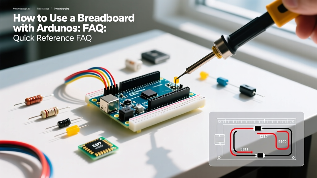

The Ultimate Quick Reference: How to Use a Breadboard with Arduino
Transitioning from blinking an onboard LED to building custom sensor networks requires a solid grasp of solderless prototyping. Learning how to use a breadboard with Arduino is the foundational skill for every embedded systems engineer and maker. Whether you are deploying an Arduino Uno R3, the newer Uno R4 Minima, or an ESP32 dev board, the breadboard remains your primary workspace for circuit validation before committing to a soldered PCB.
This quick-reference FAQ skips the fluff and dives straight into the technical realities of breadboard anatomy, power distribution limits, signal integrity, and advanced troubleshooting. According to the Arduino Official Breadboard Guide, understanding the physical limitations of solderless contacts is the difference between a stable prototype and a debugging nightmare.
Breadboard Anatomy & Specification Matrix
Before wiring your first component, you must understand the internal phosphor bronze clip architecture. The standard 830 tie-point board (often labeled MB-102 or BB830) operates on a strict 0.1-inch (2.54mm) pitch, perfectly matching standard Dual In-line Package (DIP) integrated circuits.
| Zone | Internal Connectivity | Primary Use Case | Current Limit (Per Strip) |
|---|---|---|---|
| Terminal Strips | Rows of 5 (A-E and F-J) | Mounting DIP ICs, resistors, and discrete components | ~1A - 2A (Quality dependent) |
| Center Trench | None (Physical Gap) | Isolating the left and right pins of DIP ICs | N/A |
| Power Rails | Continuous vertical columns | Distributing VCC (5V/3.3V) and GND across the board | ~2A - 3A (Watch for voltage drop) |
Expert Procurement Tip: Avoid the $2 generic clone breadboards found in bulk Amazon kits. Their internal clips fatigue quickly, leading to intermittent connections. Invest in a premium board like the BusBoard BB830 (~$7.00) or Adafruit Premium Half-Size (~$5.50), which use higher-grade beryllium copper or reinforced phosphor bronze clips that maintain tension over thousands of insertions.
Power & Grounding FAQs
How do I correctly power the breadboard rails from my Arduino?
Use the Arduino's 5V and GND pins to feed the red and blue breadboard rails, respectively. If you are working with 3.3V logic (like the ESP32 or Arduino Nano 33 IoT), use the 3.3V pin. Never connect the Arduino's 5V pin to a breadboard rail that is simultaneously being powered by an external bench supply; this will back-feed voltage into the Arduino's onboard regulator and likely destroy the microcontroller.
Can I run high-current motors directly from the breadboard's 5V rail?
No. The Arduino Uno R4's USB-C connection is typically limited to 500mA by the host PC's USB port or the onboard polyfuse. Furthermore, standard jumper wires and breadboard clips introduce parasitic resistance. Running a 12V DC motor or high-torque servo through the breadboard's 5V rail will cause severe voltage sags, resetting your microcontroller and potentially melting the jumper wire insulation. Always use an external power supply and a logic-level MOSFET or motor driver (like the L298N or TI DRV8833) for inductive loads.
Component Placement & Routing FAQs
What is the correct way to insert an LED and current-limiting resistor?
LEDs require a current-limiting resistor to prevent thermal runaway. To calculate the exact resistor value, use Ohm's Law: R = (V_source - V_forward) / I_forward.
- Source Voltage: 5V (from Arduino digital pin)
- Forward Voltage (Red LED): ~2.0V
- Target Current: 15mA (0.015A) for safe, long-life operation
- Calculation: (5 - 2.0) / 0.015 = 200Ω
Since 200Ω is not a standard E12 series value, round up to 220Ω or 330Ω. Insert the resistor in series with the LED's anode (long leg). The cathode (short leg) routes to the GND rail. As detailed in the SparkFun Breadboard Tutorial, placing the resistor on the anode side ensures the entire LED assembly sits at a safe, predictable potential relative to ground.
How should I route I2C and SPI wires on a breadboard?
High-speed digital protocols are highly susceptible to parasitic capacitance and crosstalk on solderless breadboards.
- Keep it short: Keep SDA/SCL (I2C) and MOSI/MISO/SCK (SPI) jumper wires under 10cm (4 inches).
- Avoid parallel runs: Never route I2C data lines parallel to high-current motor wires or PWM outputs; the electromagnetic interference will corrupt the data packets.
- Use Pull-ups: Breadboard traces add capacitance. If your I2C bus freezes, add 4.7kΩ pull-up resistors from SDA and SCL directly to the 5V rail to sharpen the signal rise times.
Troubleshooting Matrix: Common Breadboard Failures
When your Arduino sketch compiles perfectly but the hardware behaves erratically, the physical prototyping layer is usually at fault. Use this diagnostic matrix to isolate the issue.
| Symptom | Probable Physical Cause | Engineering Solution |
|---|---|---|
| Random button presses or sensor triggers | Floating input pin picking up ambient EMI | Enable internal pull-up via pinMode(pin, INPUT_PULLUP) or add an external 10kΩ resistor to VCC/GND. |
| Arduino randomly resets when a relay clicks | Voltage sag on the 5V rail due to inductive kickback | Add a flyback diode (1N4007) across the relay coil. Power the relay coil from a separate 5V supply. |
| Intermittent serial garbage in the monitor | Loose RX/TX jumper wire or oxidized clip | Replace the jumper wire. If using stranded wire, switch to 22 AWG solid core wire for better clip bite. |
| Analog sensor readings drift wildly | High impedance source charging breadboard capacitance | Add a 100nF ceramic decoupling capacitor between the analog input pin and GND to stabilize the ADC sample-and-hold circuit. |
Wire Selection: Solid Core vs. Stranded
A frequent mistake beginners make when figuring out how to use a breadboard with Arduino is using stranded wire or pre-crimped male-to-female jumper wires for everything. While pre-crimped dupont wires are fine for low-speed digital I/O, they are terrible for dense prototyping.
The 22 AWG Solid Core Standard
For professional-grade breadboarding, purchase a spool of 22 AWG or 24 AWG solid core copper wire (typically priced around $12-$18 for a 100ft spool from brands like Uxcell or Electrex). Use a precision wire stripper to remove exactly 1/4 inch of insulation. Solid core wire bites firmly into the breadboard's internal clips, reducing contact resistance and preventing accidental disconnects when you bump the workbench. Furthermore, solid core wire can be bent to lay flat against the breadboard surface, dramatically improving routing density and visual debugging.
Final Best Practices for Long-Term Prototyping
According to hardware design principles outlined by All About Circuits, breadboards are strictly for prototyping, not production. The contact resistance of a standard breadboard clip can range from 10mΩ when new to over 100mΩ as it ages and oxidizes. If your circuit requires precise analog measurements (like load cells or thermocouples), transition to a perfboard or custom PCB as soon as the schematic is validated. Always keep your breadboard covered when not in use to prevent dust accumulation, which acts as an insulator and increases contact resistance over time.