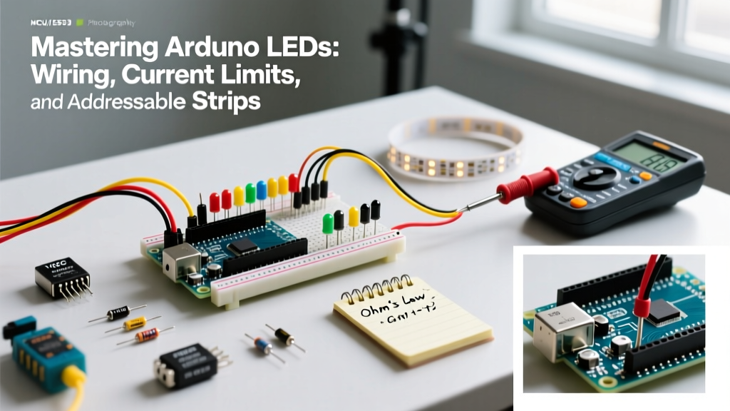

Working with Arduino LEDs is the universal rite of passage for every embedded systems engineer and maker. However, the gap between blinking a single 5mm through-hole component and driving a 500-pixel addressable matrix without causing a brownout is vast. Many tutorials gloss over the electrical realities of microcontroller pins, leading to degraded GPIO ports, flickering strips, and melted breadboard wires.
This concept explainer bypasses the basic 'blink' sketch and dives deep into the electrical engineering principles, hardware constraints, and modern addressable protocols you need to design robust lighting systems in 2026.
The Electrical Reality of Microcontroller GPIO Pins
Before wiring any component, you must understand the silicon limitations of your board. The standard Arduino Uno R3 and Nano rely on the Microchip ATmega328P microcontroller. While the internet often repeats that an Arduino pin can supply 40mA, this is the absolute maximum rating, not the recommended operating condition.
Operating an ATmega328P GPIO pin at its 40mA absolute maximum will cause long-term thermal degradation of the silicon die. Always design for the recommended 15mA to 20mA continuous limit per pin.
Furthermore, the ATmega328P groups its pins into hardware ports (PORTB, PORTC, PORTD). Each port has a cumulative current limit. For example, the total current sinking or sourcing for all pins on PORTD combined should not exceed 100mA to 200mA depending on the specific package and thermal environment. If you wire eight LEDs to PORTD and draw 20mA each, you will exceed the port limit, resulting in voltage sag and erratic logic behavior.
Calculating Current Limiting Resistors
An LED is a non-linear device with a specific Forward Voltage ($V_f$). Once the applied voltage exceeds $V_f$, current spikes exponentially, destroying the junction. You must use a current-limiting resistor. According to foundational guides from SparkFun's LED Tutorial, Ohm's Law dictates the exact resistor value needed:
R = (V_source - V_f) / I_target
Assuming a 5V Arduino logic HIGH and a safe target current of 15mA (0.015A), here is the practical matrix for standard 5mm through-hole LEDs:
| LED Color | Typical Wavelength | Forward Voltage ($V_f$) | Calculated Resistance | Standard E12 Resistor |
|---|---|---|---|---|
| Red | 620nm | 2.0V | 200Ω | 220Ω |
| Yellow | 590nm | 2.1V | 193Ω | 200Ω or 220Ω |
| Pure Green | 525nm | 3.2V | 120Ω | 120Ω |
| Blue | 470nm | 3.3V | 113Ω | 120Ω |
| White (6500K) | Broad | 3.4V | 106Ω | 110Ω |
Note: Never wire standard LEDs in parallel with a single shared resistor. Minor manufacturing variances in $V_f$ will cause one LED to hog the current, leading to thermal runaway and sequential failure.
Scaling Up: Transistors and Logic-Level MOSFETs
When your project requires high-power illumination—such as driving a 3W Cree XP-G3 star LED or a 12V analog RGB strip—an Arduino GPIO pin is entirely insufficient. You must use a switching transistor.
Why the IRLB8721 Beats the IRLZ44N
Many outdated 2015-era tutorials recommend the IRLZ44N MOSFET for 5V Arduino PWM dimming. This is a flawed recommendation. The IRLZ44N requires a Gate-to-Source Voltage ($V_{gs}$) of 10V to fully turn on and achieve its rated low $R_{DS(on)}$ (on-resistance). At the 5V output of an Arduino, it operates in its linear region, generating excessive heat and limiting current.
Instead, use the IRLB8721. It is a true logic-level N-channel MOSFET that boasts an $R_{DS(on)}$ of just 15.4mΩ at a $V_{gs}$ of 4.5V. This allows it to switch up to 20A of continuous current directly from a 5V Arduino PWM pin with virtually zero heat dissipation, costing roughly $1.20 per unit in low volumes.
The Addressable Revolution: WS2812B vs. APA102
Addressable LEDs embed a microscopic controller IC inside the LED package, allowing individual color and brightness control over a single data wire. However, not all protocols are created equal.
WS2812B (NeoPixel) Constraints
The WS2812B uses a 1-wire, 800kHz proprietary pulse protocol. Because the timing is so strict (a '1' bit is a ~800ns HIGH pulse), the Arduino must disable global interrupts while transmitting data. If your sketch relies on heavy interrupt-driven tasks (like high-speed rotary encoders or software serial), your LEDs will flicker or display random colors.
The APA102 (DotStar) Advantage
For advanced 2026 projects involving Persistence of Vision (POV) displays or high-speed camera synchronization, the APA102 is vastly superior. It uses a standard 2-wire SPI protocol (Clock and Data). This offers three massive benefits:
- No Interrupt Blocking: SPI is handled by the Arduino's hardware peripheral, freeing the CPU.
- Higher PWM Frequency: WS2812B runs at ~400Hz, which causes banding on slow-motion cameras. APA102 runs at a 20kHz PWM frequency, yielding perfectly smooth video capture.
- Global Brightness Control: APA102 features a dedicated 5-bit global brightness register, allowing you to dim the entire strip without losing 8-bit color depth resolution.
Power Injection Rules for 5V Strips
The most common failure mode in large Arduino LEDs arrays is voltage drop. A standard 60 LEDs/meter WS2812B strip draws roughly 3.6 Amps at full white (60mA per pixel). The thin copper traces on the flexible PCB (usually 2oz copper, ~1mm wide) possess significant resistance.
If you power a 5-meter strip from one end, the pixels at the far end will receive less than 3.5V, causing them to shift from white to deep red and eventually brown out the microcontroller. To solve this, consult the power injection guidelines outlined in the Adafruit NeoPixel Überguide and implement the following rules:
- Inject Power Every 50 Pixels: Run 18 AWG or 16 AWG silicone wire from your main 5V power supply (like a Mean Well LRS-300-5) to the VCC and GND pads at both ends, and the middle, of the strip.
- Use a Logic Level Shifter: WS2812B data lines require a robust 5V logic HIGH to register reliably. If you are using a 3.3V board like the Arduino Nano 33 IoT or ESP32, use a 74AHCT125 level shifter to boost the data signal.
- Common Ground: The ground of your high-current 5V power supply must be tied directly to the GND pin of your Arduino. Without a common ground reference, the data signal will float and cause chaotic pixel behavior.
Common Failure Modes and Edge Cases
The 'First Pixel is Yellow' Bug
If the first LED on your WS2812B strip is always the wrong color (often yellow or green) while the rest behave normally, this is a signal degradation issue. The Arduino's data pin struggles to drive the capacitive load of the first LED's data-in pad. Soldering a 470Ω resistor in series with the data wire, or adding a sacrificial 'dummy' pixel that you ignore in code, will clean up the signal edges.
USB Port Backfeeding
When prototyping, never power more than 10 to 15 LEDs directly from the Arduino's 5V pin while connected to a PC USB port. Standard USB 2.0 ports are limited to 500mA. Exceeding this can trip your motherboard's polyfuse or permanently damage the Arduino's onboard AMS1117-5.0 voltage regulator, which is typically rated for only 800mA to 1A of thermal dissipation.
Summary Checklist for Robust Designs
Before deploying your next lighting installation, verify your design against this hardware checklist:
- Calculated current-limiting resistors for all standard discrete LEDs.
- Verified MOSFET $V_{gs}$ threshold is compatible with 5V (or 3.3V) logic.
- Implemented 18 AWG power injection for addressable strips exceeding 50 pixels.
- Added a 1000µF decoupling capacitor across the main power supply terminals to absorb inductive voltage spikes during sudden color changes.
- Confirmed common ground between external power supplies and the MCU.
By respecting the electrical boundaries of the microcontroller and the physics of the lighting components, you transition from simply making things blink to engineering reliable, commercial-grade interactive lighting systems.
For further reading on microcontroller pin architectures, refer to the official Arduino Digital Pins documentation to understand how alternate pin functions and internal pull-up resistors can affect your custom PCB layouts.