
Core Concepts: Arduino and Breadboard Integration
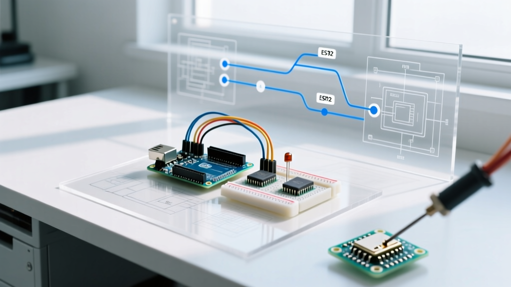
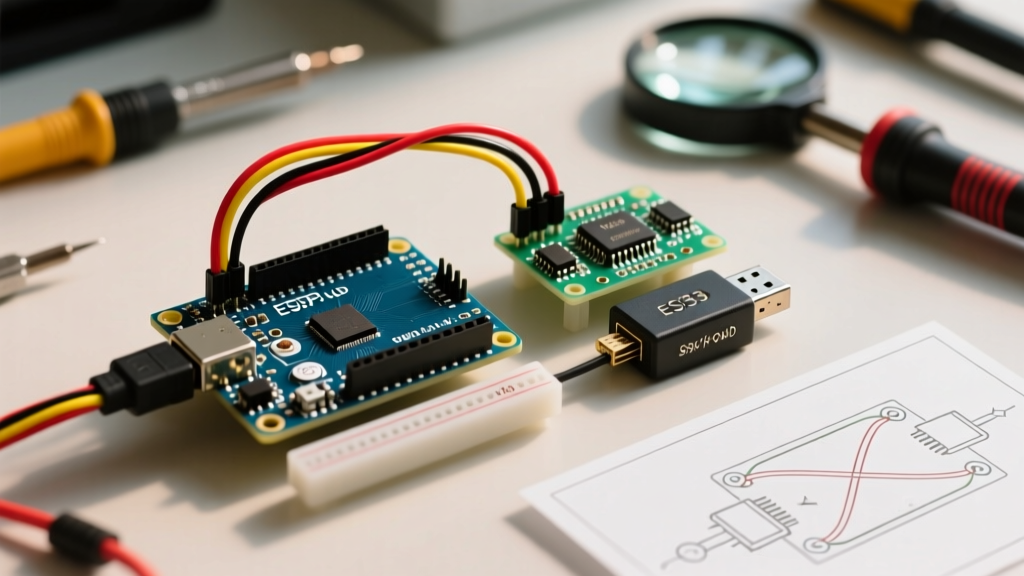
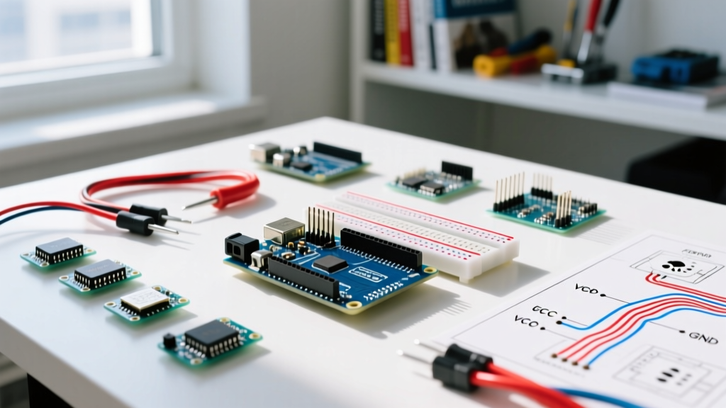
The combination of an Arduino microcontroller and a solderless breadboard remains the undisputed champion of rapid prototyping in 2026. Whether you are deploying an Arduino Uno R4 Minima for precision motor control or a Nano ESP32 for IoT sensor networks, the breadboard allows for instant circuit iteration without soldering. However, the physical limitations of solderless contacts—specifically contact resistance, parasitic capacitance, and current handling—are frequently overlooked by beginners. This quick reference FAQ addresses the most critical electrical and mechanical questions makers face when pairing an Arduino and breadboard.
Quick Reference: Power and Pin Mapping
Before routing complex logic, you must establish a stable power foundation. The table below maps standard Arduino power outputs to breadboard power rails, including critical current limits that dictate your design constraints.
| Arduino Pin | Breadboard Rail | Function | Max Current & Constraints |
|---|---|---|---|
| 5V | Red (+) | Main Logic Power | ~500mA (USB) / ~800mA (Barrel). Breadboard clips limit safe continuous draw to ~1A. |
| 3.3V | Red (+) (Secondary) | Low Voltage Logic | ~150mA (Uno R3) / ~250mA (Uno R4). Do not exceed, or the onboard regulator will thermal throttle. |
| GND | Blue/Black (-) | Common Ground | Must be shared across all split power rails. Use 22 AWG wire to minimize ground loops. |
| VIN | Red (+) (Input) | Raw Voltage In | 7-12V recommended. Bypasses onboard 5V regulator if used to feed external high-current modules. |
Arduino and Breadboard FAQ: Power & Wiring
What is the maximum current I can pull through a breadboard from an Arduino?
While the Arduino Uno R4 Minima's 5V pin can theoretically supply up to 800mA when powered via the barrel jack, the breadboard itself is often the bottleneck. Premium breadboards (like those from BusBoard Prototype Systems) use phosphor bronze clips with gold flash, rated for 1 Amp per contact point. However, the cheap, unbranded clone boards flooding the market in 2026 (often priced under $3) use low-grade steel clips. These exhibit severe voltage drops at just 300mA due to high contact resistance (often >0.5Ω per junction). Actionable Advice: If your project draws more than 400mA (e.g., driving multiple SG90 servos or high-brightness LED matrices), bypass the breadboard power rails entirely and use a dedicated external buck converter wired directly to the load.
Which wire gauge is best for Arduino and breadboard projects?
The industry standard for solderless breadboards is 22 AWG (0.64mm diameter) solid core wire.
- 22 AWG Solid Core: Provides the perfect friction fit inside standard 0.1-inch (2.54mm) pitch breadboard sockets. It pushes the internal metal leaf spring outward just enough to maintain a gas-tight connection.
- 24 AWG Solid Core: Slightly too thin (0.51mm). It will physically fit, but it often results in intermittent connections, especially if the wire is bumped.
- Stranded Wire (Any Gauge): Never insert bare stranded wire directly into a breadboard. The individual copper strands will splay, bend, and fail to make contact, or worse, break off inside the socket and permanently ruin that tie-point.
For jumper connections, invest in a pre-formed jumper wire kit or cut your own from a spool of 22 AWG PVC-hookup wire (brands like Elenco or SparkFun). Avoid the ultra-cheap, multi-colored ribbon jumper wires with molded plastic ends for critical signals; their internal crimps are notorious for failing after a few insertion cycles.
Component Placement & Signal Integrity
Why do my I2C sensors fail or drop packets on a breadboard?
I2C (Inter-Integrated Circuit) is highly susceptible to parasitic capacitance, which is inherently high on a breadboard due to the parallel metal strips running beneath the plastic housing. When you use long, parallel jumper wires to route SDA and SCL lines across a BB830 board, you create an unintentional capacitor. This rounds off the sharp square-wave edges of the I2C clock signal, leading to data corruption.
Pro-Tip for I2C on Breadboards: Keep I2C jumper wires under 4 inches (10 cm). If you must run them further, lower the I2C clock speed in your Arduino IDE from the default 400 kHz (Fast Mode) to 100 kHz (Standard Mode) using Wire.setClock(100000);. Additionally, ensure you have 4.7kΩ pull-up resistors physically located near the sensor, not near the Arduino.
How should I handle inductive loads like motors and relays?
Never drive inductive loads directly from an Arduino GPIO pin, and be highly cautious routing their power through breadboard rails. When a motor or relay coil is de-energized, it generates a massive reverse voltage spike (back-EMF). On a breadboard, this spike can arc across adjacent tie-points or travel back through the 5V rail, instantly destroying the Arduino's ATmega or Renesas RA4M1 microcontroller. Always use a flyback diode (e.g., 1N4007) placed physically across the coil terminals, and drive the load via a MOSFET (like the IRLZ44N) or an optocoupler.
Troubleshooting Matrix: Common Breadboard Failures
When your Arduino sketch compiles perfectly but the hardware behaves erratically, use this diagnostic matrix to isolate the physical layer.
| Symptom | Probable Root Cause | Actionable Fix |
|---|---|---|
| Arduino resets randomly when a sensor triggers | Brownout due to voltage drop on breadboard power rails. | Measure 5V rail with a multimeter under load. Move high-draw components to an external power supply sharing a common GND. |
| ADC (Analog) readings are noisy or drifting | High contact resistance or ground loops on the breadboard. | Use a dedicated GND wire for the analog sensor. Add a 0.1μF ceramic capacitor between the analog pin and GND. |
| I2C OLED display flickers or fails to initialize | Parasitic capacitance or weak pull-up resistors. | Shorten SDA/SCL wires. Add 4.7kΩ pull-ups to 3.3V/5V. Reduce I2C bus speed. |
| Intermittent connection when tapping the board | Oxidized or fatigued metal clips inside the breadboard. | Replace the breadboard. Clean component legs with isopropyl alcohol before insertion. |
Mechanical Stability & Environmental Factors
A frequent point of failure in Arduino and breadboard setups is mechanical stress. The Arduino Uno R3 and R4 are relatively heavy compared to a bare breadboard. When you plug in stiff USB cables or thick jumper wires, the leverage can lift the Arduino's headers right out of the breadboard sockets, causing instant ground faults or short circuits. To mitigate this, use a 3D-printed mounting bezel or double-sided foam tape to secure the microcontroller to the workbench. Furthermore, environmental humidity can rapidly oxidize the exposed metal clips of cheap breadboards. If you are prototyping in a non-climate-controlled garage or outdoor environment, consider applying a thin layer of dielectric grease to the component leads before insertion to prevent galvanic corrosion, or use a sealed project box with silica gel desiccant packs once the prototype phase is complete.
Expert Sourcing & Quality Control for 2026
Not all breadboards are created equal. As supply chains have shifted, the market is saturated with substandard clones. For professional prototyping or permanent classroom setups, source your boards from reputable manufacturers like BusBoard Prototype Systems (BPS) or 3M. A genuine BPS BB830 (830 tie-points) typically costs between $8.00 and $12.00, whereas generic clones sell for $2.00 to $4.00. The premium models feature nickel-plated phosphor bronze contacts that maintain spring tension for over 1,000 insertion cycles, whereas clones often fail after 50 cycles.
For further reading on microcontroller hardware specifications and prototyping best practices, consult the Arduino Official Product Lineup and the comprehensive SparkFun Breadboard Tutorial. Mastering the physical interface between your Arduino and breadboard is the first step toward building robust, reliable electronic systems.