
For most makers, the HC-SR04 ultrasonic sensor is the undisputed starting point for distance measurement. At roughly $2 per unit, it is the 'hello world' of proximity sensing. However, when you transition from a controlled workbench environment to deploying a real-world arduino sonar system outdoors, in humid greenhouses, or on mobile robotics platforms, the classic HC-SR04 quickly becomes a critical point of failure. Condensation on the metal mesh, dust accumulation, and 5V logic incompatibilities with modern 3.3V microcontrollers force a necessary migration.
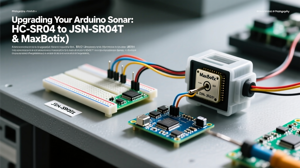
In 2026, the maker ecosystem has matured, and upgrading your ultrasonic array is no longer just about buying a more expensive sensor—it is about matching acoustic beam patterns, IP ratings, and interface protocols to your specific operational environment. This guide provides a comprehensive migration path from the baseline HC-SR04 to the waterproof JSN-SR04T, and ultimately to industrial-grade MaxBotix modules.
Migration Matrix: Choosing Your Next Sensor
Before ripping out your existing wiring, it is crucial to understand the physical and electrical differences between these three tiers of ultrasonic sensors. The blind zones and beam widths will drastically alter how you mount and code your array.
| Feature | HC-SR04 (Baseline) | JSN-SR04T V2.0 (Tier 1) | MaxBotix MB7389 (Tier 2) |
|---|---|---|---|
| Typical Cost | $1.50 - $2.50 | $6.00 - $9.00 | $45.00 - $55.00 |
| Blind Zone | ~2 cm | ~20 cm | ~30 cm (HRXL models) |
| Max Range | 400 cm | 600 cm | 500 cm |
| Beam Width | ~15° | ~30° | ~10° (Highly directional) |
| Environmental Rating | None (Open mesh) | IP67 (Sealed transducer) | IP67 (Weather-resistant) |
| Operating Voltage | 5V DC | 3.3V - 5V DC | 2.5V - 5.5V DC |
| Output Interface | PWM (Trigger/Echo) | PWM (Trigger/Echo) | Analog, PWM, RS232 Serial |
Tier 1 Migration: Upgrading to the JSN-SR04T
The JSN-SR04T is the most logical first step for upgrading an arduino sonar project intended for outdoor or damp environments. By separating the transducer from the control board via a 2.5-meter shielded cable, you can mount the sealed, waterproof transducer in harsh conditions while keeping the logic board safely inside an enclosure.
The V2.0 Hardware Revision and the 470µF Trap
If you are migrating from older tutorials, be aware of the hardware revisions. The original V1.0 JSN-SR04T boards featured a massive 470µF electrolytic capacitor that often caused brownouts on standard Arduino Uno 5V rails during the initial acoustic burst, leading to MCU resets. The current V2.0 revision (widely available in 2026) has replaced this with a more efficient power management circuit, but it introduces a new quirk: the Echo pin is highly sensitive to floating states.
When migrating your wiring, you must add a 10kΩ pull-up resistor between the Echo pin and VCC (3.3V or 5V, matching your MCU). Without this, electromagnetic interference from nearby motors or relays will induce phantom echoes, causing your distance readings to spike to maximum range randomly.
The 3.3V Logic Trap
Modern maker projects heavily favor 3.3V microcontrollers like the ESP32-S3, Raspberry Pi Pico (RP2040), or Arduino Nano 33 IoT. The HC-SR04 strictly requires 5V to trigger reliably, which often led makers to dangerously wire 5V signals directly into 3.3V GPIO pins. According to SparkFun's guide on logic levels, feeding a 5V echo signal into a 3.3V tolerant pin will eventually degrade the silicon and destroy the GPIO bank.
The Migration Fix: Use a bidirectional logic level shifter based on the BSS138 MOSFET (costing about $1.50) or a dedicated TXS0108E chip. Connect the high-voltage side to the JSN-SR04T Echo pin, and the low-voltage side to your ESP32 GPIO. This ensures safe, reliable translation without the voltage drop associated with simple resistor-divider networks, which can mush the sharp rising edges required for accurate timing.
Tier 2 Migration: Industrial Precision with MaxBotix
When your project requires mapping complex environments, avoiding specular reflections off angled walls, or operating in high-acoustic-noise environments, you must migrate to a MaxBotix sensor, such as the MB7389 HRXL-MaxSonar-WR. These sensors utilize sophisticated internal DSP (Digital Signal Processing) to filter out acoustic noise and provide a highly focused 10° beam width.
Choosing the Right Output Protocol
Unlike the HC-SR04, MaxBotix sensors offer three simultaneous outputs. Migrating requires choosing the right protocol for your specific MCU architecture:
- Analog Voltage: Outputs a scaled voltage (e.g., Vcc/512 per inch). While easy to read with an ADC, analog signals are highly susceptible to voltage drop and noise over cables longer than 1 meter. Avoid this for distributed sonar arrays.
- Pulse Width (PWM): Similar to the HC-SR04 but without needing a trigger pin. The sensor continuously pings and outputs a high pulse where 1µs equals 1mm. This is excellent for hardware interrupt parsing.
- RS232 Serial: Outputs asynchronous serial data. Note that MaxBotix uses inverted RS232 logic, not standard TTL UART. If you are connecting to an Arduino Mega or ESP32 hardware UART, you must either use a hardware inverter chip (like a 74HC04) or utilize the MCU's software UART library with the inverted signal flag enabled.
Refactoring Your Codebase: Beyond pulseIn()
The most common mistake when upgrading an arduino sonar array is retaining legacy code that relies on the blocking pulseIn() function. Sound travels at roughly 343 meters per second in air at 20°C. If you are measuring a distance of 5 meters, the acoustic round-trip takes approximately 29 milliseconds. If your robot has four sonar sensors and you ping them sequentially using pulseIn(), your main loop is blocked for over 120 milliseconds per cycle. In a fast-moving robotic application, this latency is catastrophic.
Expert Migration Tip: When migrating to multiple JSN-SR04T or MaxBotix sensors, abandonpulseIn(). Instead, utilize the NewPing library's timer-based event system, or write a custom Hardware Interrupt Service Routine (ISR) usingattachInterrupt(digitalPinToInterrupt(echoPin), readEcho, RISING). This allows your MCU to process motor control and SLAM algorithms while the acoustic pulses are in transit.
Handling the Expanded Blind Zone
Both the JSN-SR04T and MaxBotix MB7389 possess significantly larger blind zones (20cm and 30cm, respectively) compared to the HC-SR04's 2cm blind zone. This physical limitation is due to the acoustic dampening required to stop the heavy, sealed transducer cones from ringing after the 40kHz burst is emitted. When migrating your physical CAD mounts or sensor brackets, you must implement sensor fusion overlap. Mount a secondary short-range sensor (like a Time-of-Flight VL53L1X laser sensor, which has a 0cm blind zone and 400cm range) directly adjacent to your ultrasonic transducer. Use a simple Kalman filter or a weighted average in your code to seamlessly hand off distance tracking from the ToF sensor to the ultrasonic sensor once the object passes the 25cm threshold.
Summary Checklist for Your Upgrade
- Audit your environment: If humidity or dust is present, immediately retire open-mesh HC-SR04 sensors.
- Verify MCU logic levels: Install BSS138 logic shifters if migrating 5V echo lines to 3.3V ESP32 or RP2040 boards.
- Add pull-up resistors: Place 10kΩ resistors on all JSN-SR04T V2.0 echo lines to prevent phantom EMI triggers.
- Refactor blocking code: Replace
pulseIn()with hardware interrupts or the NewPing timer library to reclaim CPU cycles. - Compensate for blind zones: Pair long-range ultrasonic sensors with short-range ToF or IR sensors to eliminate the 20-30cm dead zone.
Upgrading your ultrasonic hardware is only half the battle. By addressing the electrical interface, acoustic physics, and non-blocking code architecture, your migrated arduino sonar system will achieve the reliability required for professional-grade robotics and environmental monitoring in 2026 and beyond.