
The Serial2 Dilemma: Why Your Secondary UART is Failing
When integrating secondary peripherals like GPS modules, cellular modems, or secondary microcontrollers, relying on software-based serial emulation is a recipe for dropped packets and CPU blocking. The native hardware solution is invoking Serial2.begin(). However, makers frequently hit two distinct walls: aggressive compilation errors stating the object is undeclared, or silent runtime failures where data transmits but arrives as garbage characters.
As of 2026, the maker ecosystem is heavily fragmented between legacy 8-bit AVR architectures and modern 32-bit RISC-V/Xtensa chips. Troubleshooting Serial2.begin() requires a precise understanding of your target silicon's USART (Universal Synchronous/Asynchronous Receiver-Transmitter) matrix. This guide dissects the exact hardware and software failure modes for the two most common boards utilizing secondary serial ports: the Arduino Mega 2560 and the ESP32 family.
Compilation Faults: 'Serial2' Was Not Declared in This Scope
If your Arduino IDE throws a red compilation error the moment you type Serial2.begin(9600);, you are attempting to call a hardware register that does not exist on your selected microcontroller.
The standard Arduino Uno and Nano utilize the ATmega328P. This chip possesses exactly one hardware USART, mapped to Serial (pins 0 and 1). The compiler inherently strips out Serial1, Serial2, and Serial3 definitions for these boards to save flash memory. To use multiple serial streams on an ATmega328P, you must use the SoftwareSerial library, which comes with severe baud-rate limitations (typically capping at 57600 bps reliably).
Hardware UART Availability Matrix
| Microcontroller Board | Core Silicon | Hardware UART Count | Serial2 Supported? | Typical 2026 Clone Price |
|---|---|---|---|---|
| Arduino Uno R3 / Nano | ATmega328P | 1 | No (Requires SoftwareSerial) | $6 - $9 |
| Arduino Mega 2560 Rev3 | ATmega2560 | 4 | Yes (Pins 16 & 17) | $14 - $18 |
| Arduino Due | SAM3X8E (ARM Cortex-M3) | 4 | Yes (Pins 16 & 17) | $22 - $28 |
| ESP32 DevKit V1 | ESP32-WROOM-32E | 3 | Yes (Requires Pin Mapping) | $4 - $7 |
| Raspberry Pi Pico | RP2040 | 2 (PIO capable) | Yes (Via Serial2 object) | $4 - $6 |
Source: Arduino Official Language Reference
Scenario A: Arduino Mega 2560 Wiring & Logic Level Failures
If you are compiling for the Mega 2560 and the code uploads successfully, but your secondary device (e.g., a SIM800L GSM module or u-blox NEO-M8N GPS) is not responding, the issue is almost certainly physical wiring or logic-level mismatch.
The TX/RX Crossover Mistake
On the Arduino Mega 2560, the hardware pins for Serial2 are strictly hardcoded in the silicon:
- TX2 (Transmit): Digital Pin 16
- RX2 (Receive): Digital Pin 17
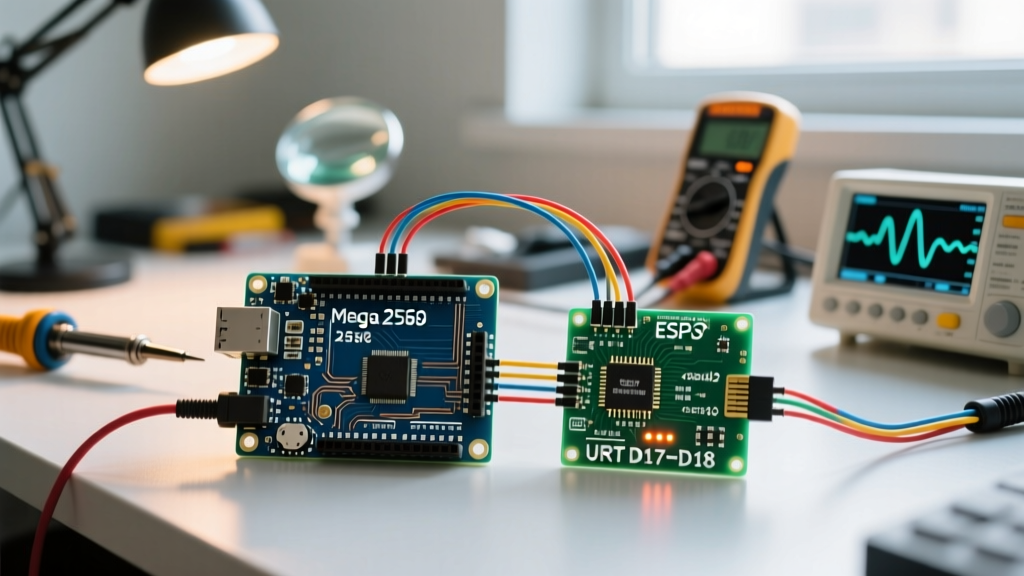
A pervasive beginner error is wiring TX to TX and RX to RX. Serial communication requires a crossover: Pin 16 (TX2) must connect to the peripheral's RX pin, and Pin 17 (RX2) must connect to the peripheral's TX pin.
The 5V vs 3.3V Logic Trap
The ATmega2560 operates at 5V logic. Modern peripherals, including almost all ESP-series Wi-Fi modules, cellular modems, and advanced GPS units, operate at 3.3V logic and are not 5V tolerant. Feeding 5V from the Mega's Pin 16 directly into a 3.3V ESP-01S RX pin will degrade the peripheral's silicon over time or cause immediate latch-up failure.
Expert Fix: Never use a simple resistor voltage divider for high-speed UART lines. The parasitic capacitance of the resistor network will round off the square waves, causing bit-errors at 115200 baud. Instead, use a dedicated BSS138 MOSFET-based bi-directional logic level converter (available for ~$1.50 on modern component marketplaces) to safely translate the 5V TX2 signal down to 3.3V.
Scenario B: ESP32 UART2 Pin Mapping & PSRAM Conflicts
The ESP32 architecture is vastly more flexible than the AVR lineup, featuring a GPIO matrix that allows almost any UART to be routed to almost any pin. However, this flexibility introduces severe edge cases when invoking Serial2.begin().
The Default Pin Conflict (WROVER vs WROOM)
By default, the ESP32 Arduino core maps UART2 to GPIO 16 (RX2) and GPIO 17 (TX2). If you are using a standard ESP32-WROOM-32 module, this works perfectly. However, if you are using an ESP32-WROVER module (which includes external PSRAM for camera or audio buffering), GPIO 16 and 17 are internally hardwired to the PSRAM chip.
Calling Serial2.begin(115200) on a WROVER board without remapping the pins will result in the UART peripheral fighting the SPI bus for PSRAM access, leading to immediate kernel panics, bootloops, or silent data corruption.
The Solution: Explicit Pin Routing
To bypass default pin conflicts, you must use the extended ESP32 Serial2.begin() syntax, which allows you to define the serial configuration and explicit GPIO pins. As documented in the Espressif UART API Guide, the syntax is:
Serial2.begin(baudrate, config, rxPin, txPin);Working Code Implementation:
// Safe UART2 initialization for ESP32 (Avoids GPIO 16/17 PSRAM conflicts)
#define RXD2 26
#define TXD2 27

void setup() {
  // Initialize USB Serial for debugging
  Serial.begin(115200);

  // Initialize Serial2 on custom pins
  // SERIAL_8N1 = 8 data bits, No parity, 1 stop bit
  Serial2.begin(115200, SERIAL_8N1, RXD2, TXD2);

  Serial.println('Serial2 initialized on GPIO 26/27');
}

void loop() {
  if (Serial2.available()) {
    Serial.write(Serial2.read());
  }
}
Scenario C: Baud Rate Drift & The 16MHz Crystal Error
If your wiring is perfect and your pins are correctly mapped, but your serial monitor outputs unreadable garbage characters (e.g., ??$#@!), you are experiencing baud rate drift. This is a hardware-level timing issue inherent to the Arduino Mega 2560.
The ATmega2560 relies on a 16MHz external crystal oscillator to calculate UART timing divisions. At standard baud rates like 9600, the math divides cleanly. However, at 115200 baud, the 16MHz clock cannot divide evenly into the required bit-timing windows. This results in an actual transmission rate of roughly 117647 baud—a -2.1% error margin.
While many modern USB-to-Serial chips (like the FTDI FT232RL) can tolerate a 2% drift, highly sensitive industrial equipment or strict cellular modems will reject the packets, resulting in framing errors.
How to Fix Baud Rate Drift
- Drop the Baud Rate: Change both the Mega and the peripheral to
57600or38400. The 16MHz crystal divides into these numbers with near 0% error. - Upgrade the Silicon: If your application strictly requires 115200 baud or higher (e.g., streaming NMEA sentences from a high-speed RTK GPS), migrate your project to an ESP32 or Arduino Due. The ESP32 utilizes a 40MHz crystal and an advanced fractional baud-rate generator, reducing the 115200 baud error margin to less than 0.1%.
Advanced Troubleshooting: Buffer Overflows
A final, insidious failure mode occurs when Serial2.begin() works, but you randomly lose chunks of incoming data. This is a buffer overflow.
The Arduino Mega 2560 allocates a meager 64-byte hardware receive buffer for each serial port. If your peripheral sends a 120-byte JSON payload in a single burst, and your loop() function is temporarily blocked by a delay() or a slow LCD screen update, the 65th byte will overwrite the buffer, and data will be permanently lost.
The Fix: Never use blocking code when reading from Serial2. Implement a non-blocking ring buffer in your software to catch incoming bytes instantly:
String serialBuffer = '';

void loop() {
  while (Serial2.available() > 0) {
    char c = Serial2.read();
    if (c == '\n') {
      processPayload(serialBuffer);
      serialBuffer = '';
    } else {
      serialBuffer += c;
    }
  }
  // Perform other non-blocking tasks here
}
Summary Diagnostic Checklist
Before assuming your microcontroller is defective, run through this rapid diagnostic sequence:
- Step 1: Verify IDE Board Selection. Ensure you haven't accidentally left the IDE set to 'Arduino Uno' while compiling for a Mega.
- Step 2: Confirm physical crossover. TX2 (Pin 16) goes to Peripheral RX. RX2 (Pin 17) goes to Peripheral TX.
- Step 3: Measure logic levels with a multimeter or oscilloscope. Ensure 5V AVRs are using a MOSFET logic converter when talking to 3.3V modules.
- Step 4: ESP32 users must explicitly define
rxPinandtxPinin thebegin()function to avoid PSRAM bus collisions on WROVER modules. - Step 5: Lower baud rate to 57600 to rule out 16MHz crystal timing drift.
Mastering hardware serial routing separates novice tinkerers from reliable embedded systems engineers. By respecting the physical limitations of the silicon and the electrical realities of logic levels, Serial2.begin() transforms from a source of frustration into a robust pipeline for complex multi-device architectures.