
The Enduring Legacy of the Arduino Mini Pro in 2026
While the maker community frequently searches for the Arduino Mini Pro, the official designation for this iconic, stripped-down microcontroller board is the Arduino Pro Mini. Originally designed by SparkFun and later adopted by the broader open-source hardware ecosystem, this board remains a cornerstone of low-power IoT and battery-operated DIY projects in 2026. Despite SparkFun officially retiring their manufacturing run of the original boards a few years ago, high-quality ATmega328P clones continue to dominate the market, typically priced between $2.50 and $4.50 on major electronics marketplaces.
Because the board lacks an onboard USB-to-Serial converter to save space, power, and cost, configuring and uploading sketches requires an external FTDI adapter. This guide provides a comprehensive, expert-level configuration workflow to ensure your 3.3V or 5V variants communicate flawlessly with the Arduino IDE.
Hardware Variants: 3.3V/8MHz vs 5V/16MHz
The most common configuration error occurs when developers mismatch the IDE board settings with the physical hardware. The ATmega328P microcontroller behaves entirely differently depending on its clock speed and operating voltage. Pushing 5V into a 3.3V board will instantly destroy the onboard voltage regulator and potentially fry connected 3.3V sensors (like the popular BME280 or ESP-01 modules).
| Specification | 3.3V Variant (8MHz) | 5V Variant (16MHz) |
|---|---|---|
| Crystal Oscillator | 8.000 MHz | 16.000 MHz |
| Operating Voltage | 3.3V (Max 3.8V on RAW pin) | 5.0V (Max 12V on RAW pin) |
| Max I/O Pin Current | ~10mA per pin (Safe) | ~20mA per pin (Absolute Max) |
| Serial Baud Rate Limit | 57600 bps (Standard) | 115200 bps (Standard) |
| Onboard Regulator | 3.3V LDO (Micrel MIC5219) | 5.0V LDO (Micrel MIC5219) |
Expert Warning: Never attempt to run the 3.3V/8MHz variant at 16MHz by simply changing the IDE fuse bits. The ATmega328P datasheet explicitly states that 16MHz operation requires a minimum of 4.5V. Doing so will result in erratic behavior, corrupted EEPROM writes, and failed uploads.
Step-by-Step Arduino IDE Configuration
To configure the Arduino IDE (version 2.x or the classic 1.8.x) for your board, follow these precise steps. The Pro Mini does not require custom board manager URLs; it is natively supported by the core Arduino AVR package.
- Install the AVR Core: Navigate to Tools > Board > Boards Manager. Search for 'Arduino AVR Boards' and ensure you are running the latest stable release (1.8.6 or newer).
- Select the Board: Go to Tools > Board > Arduino AVR Boards and select Arduino Pro or Pro Mini.
- Match the Processor: This is the most critical step. Go to Tools > Processor and select either ATmega328P (3.3V, 8 MHz) or ATmega328P (5V, 16 MHz) to match the physical crystal on your board.
- Select the Port: Plug in your USB-to-Serial adapter. Go to Tools > Port and select the COM port (Windows) or /dev/tty.usbserial (macOS) associated with your adapter.
Wiring the FTDI Adapter (The 6-Pin Header)
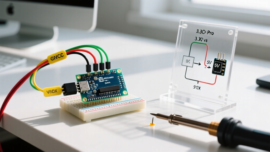
The board utilizes a standard 6-pin FTDI header. However, pinouts on clone FTDI adapters (FT232RL or CH340G chips) vary wildly. You must wire based on signal function, not just physical position.
| Pro Mini Pin | Signal Name | FTDI Adapter Pin | Function & Notes |
|---|---|---|---|
| 1 | GRN (DTR) | DTR | Data Terminal Ready. Triggers auto-reset via 0.1µF capacitor. |
| 2 | TXO | RXI / RX | Transmit Out. Connects to adapter Receive In. |
| 3 | RXI | TXO / TX | Receive In. Connects to adapter Transmit Out. |
| 4 | VCC | VCC (3.3V or 5V) | Power input. Must match board voltage! |
| 5 | GND | GND | Common Ground. |
| 6 | BLK (GND) | CTS / GND | Secondary Ground. CTS is unused for standard uploads. |
For an authoritative visual reference and historical context on the board's design, refer to the SparkFun Pro Mini Hookup Guide, which remains the gold standard for hardware mapping.
The Auto-Reset Capacitor Edge Case
The Pro Mini relies on a 0.1µF capacitor placed between the DTR pin and the ATmega328P Reset pin to automatically trigger the bootloader when a serial connection opens. If your clone FTDI adapter lacks the DTR pin (some cheap CH340 boards break out RTS instead), the IDE will hang on the 'Uploading...' message and eventually throw a Programmer is not responding error.
The Manual Reset Workaround: If DTR is unavailable, connect the RTS pin to the Pro Mini's Reset pin via a 0.1µF capacitor. When the upload reaches 100% compilation and the IDE console switches to 'Uploading', physically press and release the tiny tactile reset button on the Pro Mini. Timing is critical; you must trigger the reset within 1.5 seconds of the upload phase beginning.
Troubleshooting Common Upload Failures
Even with perfect wiring, configuration issues frequently stall development. Use this diagnostic matrix to resolve upload failures.
| Error Message | Root Cause | Actionable Solution |
|---|---|---|
| avrdude: stk500_recv(): programmer is not responding | Wrong board voltage/clock selected in IDE, or missing DTR auto-reset. | Verify 3.3V/8MHz vs 5V/16MHz selection. Try the manual reset button workaround. |
| avrdude: ser_open(): can't open device | FTDI adapter driver missing or port locked by another application. | Install CH340 or FT232 drivers. Close serial monitors in other IDE instances. |
| wrong board? (Expected signature 0x1E950F) | Board has an ATmega168 chip, but IDE is set to ATmega328P. | Read the laser etching on the main black IC. Select ATmega168 in the Tools menu if present. |
| Timeout communicating with programmer | TX/RX lines crossed incorrectly or baud rate mismatch. | Swap TX and RX wires. Ensure Serial.begin() matches the board's max baud limit. |
Advanced Configuration: Ultra-Low Power Optimization
The primary reason engineers choose the Pro Mini over the standard Arduino Uno or Nano in 2026 is its potential for ultra-low power consumption. Out of the box, a clone Pro Mini draws roughly 15mA to 25mA at 5V, which is far too high for battery-powered nodes meant to last months on a single 18650 cell.
Hardware Modifications for Sleep Modes
To achieve the microamp (µA) sleep currents documented in Nick Gammon's seminal AVR power saving guide, you must physically modify the board to eliminate parasitic drain:
- Remove the Power LED: The onboard red LED and its current-limiting resistor draw a constant 3mA to 5mA. Use a hot air rework station or a fine-tipped soldering iron to desolder the LED or physically scrape the LED off the PCB with an X-Acto knife.
- Remove the Voltage Regulator: If you are powering the board directly from a 3.3V source (like two AA batteries or a 3.3V LiFePO4 cell), the onboard LDO regulator introduces a quiescent current drain of ~1mA to 3mA. Desolder the 3-pin regulator entirely, or cut the trace connecting the RAW pin to the regulator input.
- Disable Brown-Out Detection (BOD): The BOD circuit monitors voltage and resets the chip if it drops too low, but it consumes ~18µA continuously. You can disable BOD via software using the
sleep_bod_disable()macro right before enteringsleep_mode(), or permanently disable it by burning custom fuse bits using an ISP programmer (like a USBasp).
Bypassing the Regulator via the RAW Pin
A common point of confusion is the RAW pin versus the VCC pin. According to the official Arduino hardware documentation, the RAW pin feeds directly into the onboard voltage regulator.
If you are using the 5V variant, you can supply anywhere from 5.5V to 12V into the RAW pin. However, if you are powering a 3.3V project from a 3.7V LiPo battery, feeding 3.7V into the RAW pin will fail; the LDO requires a dropout voltage of at least 0.5V to 1.0V to regulate properly. In this scenario, you must bypass the regulator entirely and inject the 3.7V directly into the VCC pin. The ATmega328P can safely handle up to 4.0V when running at 8MHz, making direct LiPo connection to VCC a highly efficient configuration for portable dataloggers.
Summary Checklist for Flawless Deployment
Before deploying your Arduino Mini Pro into a permanent enclosure, run through this final configuration checklist:
- Verify physical crystal matches IDE Processor selection (8MHz vs 16MHz).
- Confirm FTDI adapter voltage switch is set correctly (if using a dual-voltage adapter).
- Ensure TX connects to RX, and RX connects to TX (crossed serial lines).
- Test the auto-reset function; if it fails, prepare for manual reset timing or add a 0.1µF capacitor to DTR.
- For battery nodes, scrape off the power LED and verify sleep currents with a multimeter in µA mode.
By mastering these hardware and software configurations, you transform this inexpensive, bare-bones microcontroller into a highly reliable, ultra-efficient engine for your most demanding embedded projects.