
Introduction to Arduino-Based EMS Diagnostics
Developing a custom Arduino engine management system (EMS) or tuning an open-source ECU like Speeduino is one of the most rewarding projects in the maker and automotive engineering space. However, replacing a factory ECU with a microcontroller-based solution introduces severe real-time processing and electrical noise challenges. When an Arduino-based ECU fails, the consequences range from a simple engine stall to catastrophic over-revving or hydro-locking due to stuck-open injectors.
This guide provides deep-level error diagnosis for Arduino engine management systems, focusing on the electrical and computational edge cases that cause timing drift, missed trigger teeth, and injector saturation. Whether you are running an ATmega2560-based Speeduino v0.4 board or a custom STM32/Teensy 4.1 setup, understanding these failure modes is critical for reliable operation.
The 4 Most Critical Hardware & Software Errors
1. Trigger Signal Dropout and Missed Teeth
The foundation of any Arduino engine management system is the crankshaft position sensor (CKP) and camshaft position sensor (CMP). Most setups use a 36-1 or 60-2 reluctor wheel paired with a Variable Reluctance (VR) sensor. A common beginner mistake is wiring a raw VR sensor directly to an Arduino digital input pin.
- The Failure Mode: VR sensors output an AC sine wave whose amplitude scales with RPM. At cranking speeds (150 RPM), the signal might be 0.5V. At 7,000 RPM, the signal can exceed 80V peak-to-peak. Feeding this into an ATmega2560 pin will instantly destroy the microcontroller's internal clamping diodes and fry the port.
- The Diagnosis: If your TunerStudio log shows random "Sync Loss" or "Missed Teeth" errors at high RPM, your signal conditioning circuit is failing. The Arduino's
attachInterrupt()function is likely being flooded with noise or the voltage is sagging below the logic threshold. - The Fix: You must use a dedicated VR signal conditioner IC. The MAX9926 or the older LM1815 are industry standards. These chips convert the erratic AC sine wave into a clean 0-5V square wave with built-in hysteresis to reject electromagnetic interference (EMI) from the alternator and ignition coils.
2. Microcontroller Brownout and Reset Loops
Automotive electrical systems are notoriously hostile. While a car battery is nominally 12V, an running alternator outputs 13.8V to 14.4V. Furthermore, inductive load dumps from the fuel pump relay or AC compressor clutch can send transient voltage spikes exceeding 40V (as defined by ISO 7637-2).
If you are powering your Arduino Mega 2560 via the onboard barrel jack or VIN pin, you are relying on the onboard NCP1117 linear voltage regulator. This regulator must dissipate the voltage difference as heat. At 14V input and a 150mA draw (common when driving status LEDs and serial interfaces), the regulator will overheat and trigger its internal thermal shutdown. The Arduino will reboot mid-operation, causing the engine to instantly cut out.
Critical Safety Warning: Never rely on the Arduino's onboard linear regulator for automotive EMS applications. A mid-drive reset loop can cause the ignition to fire at the wrong time, potentially causing severe engine knock or backfires.
The Fix: Bypass the onboard regulator entirely. Use an automotive-grade DC-DC buck converter (such as the LM2596HV configured for 5V) or an automotive LDO like the LM2940CT-5.0, which features built-in load dump protection and reverse battery protection. Feed the clean 5V directly into the Arduino's 5V pin.
3. Injector Flyback and IGBT Saturation
Fuel injectors are highly inductive loads. When the microcontroller commands the injector driver (usually a MOSFET or IGBT) to turn off, the collapsing magnetic field generates a massive reverse voltage spike known as inductive kickback ($V = L \frac{di}{dt}$). Without proper clamping, this spike can exceed 100V, arcing across the transistor and feeding back into the Arduino's 12V rail, resetting the ECU.
The Diagnosis: If your Arduino resets exactly when the fuel injectors fire, or if your injector driver transistors are running excessively hot and failing, you have a flyback clamping issue. Additionally, if you are using standard logic-level MOSFETs (like the IRLZ44N) without adequate gate drive current, the MOSFET spends too much time in the linear (saturation) region, generating immense heat.
The Fix: Upgrade your injector drivers to automotive ignition IGBTs with built-in active clamping, such as the ISL9V3040S3S or VND7040. These chips are specifically designed to safely absorb the flyback energy of fuel injectors and ignition coils, protecting the low-voltage logic side of your Arduino EMS.
4. TunerStudio Serial Buffer Overflows
Real-time tuning requires high-speed serial communication between the Arduino ECU and the TunerStudio software on your laptop. The Speeduino protocol typically operates at 115,200 baud. However, the ATmega2560 hardware serial buffer is only 64 bytes. If the microcontroller is heavily loaded with calculating fuel maps, idle control (PID loops), and reading analog sensors, it may fail to service the serial interrupt in time.
The Diagnosis: You will experience "Communication Timeout" errors in TunerStudio, or the real-time dashboards will freeze while the engine continues to run normally. This is a software bottleneck, not a hardware failure.
The Fix: Implement a circular buffer for serial transmission in your sketch, or upgrade your microcontroller architecture. Moving from an 8-bit ATmega2560 to a 32-bit Teensy 4.1 or STM32F407 provides vastly superior clock speeds (600MHz vs 16MHz) and hardware DMA (Direct Memory Access) channels, completely eliminating serial buffer overflows.
Microcontroller Architecture Comparison for EMS
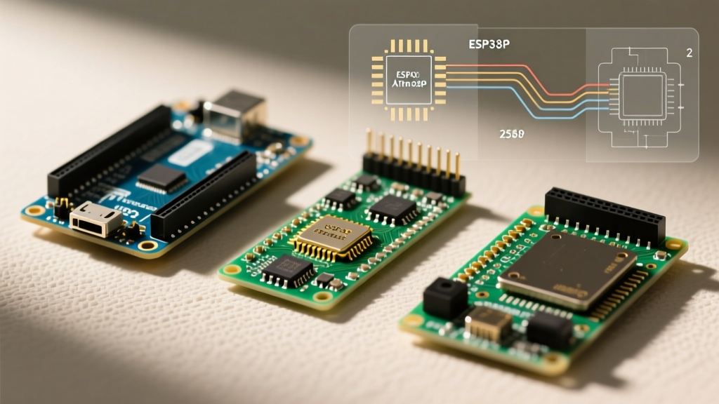
Choosing the right brain for your Arduino engine management system dictates your diagnostic ceiling. Below is a comparison of the most common MCUs used in open-source ECUs as of 2026.
| Microcontroller | Clock Speed | Interrupt Latency | Injector Channels | Best Use Case |
|---|---|---|---|---|
| ATmega2560 (Arduino Mega) | 16 MHz | High (~2.5 µs) | Up to 4 (Sequential) | Low-RPM naturally aspirated engines, beginners, Speeduino v0.4 |
| STM32F407 (Black Pill/Custom) | 168 MHz | Low (~0.1 µs) | Up to 8 (Sequential) | High-RPM, forced induction, V6/V8 sequential fuel/spark |
| Teensy 4.1 (NXP i.MX RT1062) | 600 MHz | Ultra-Low | 12+ (Advanced) | R&D, rapid prototyping, complex traction control logic |
Oscilloscope Debugging Workflow
When diagnosing an Arduino engine management system, a multimeter is virtually useless due to the high-speed transient nature of the signals. You must use a digital storage oscilloscope (DSO) or an automotive PicoScope. Follow this step-by-step workflow to isolate timing errors:
- Probe the Crank Sensor Raw Signal: Connect Channel A to the raw VR sensor output. Verify the AC amplitude crosses zero cleanly and check for missing teeth on the reluctor wheel. Look for high-frequency noise riding on the sine wave.
- Probe the Conditioned Signal: Connect Channel B to the output of the MAX9926/LM1815 conditioner (the Arduino interrupt pin). Verify it is a crisp 0-5V square wave. Measure the delay between the raw zero-crossing and the square wave edge; excessive delay indicates incorrect hysteresis resistor values.
- Probe the Injector Driver Gate: Connect Channel C to the gate of the injector MOSFET/IGBT. Verify the Arduino is sending a sharp 5V pulse. If the rise time is slow (sloped instead of square), your Arduino pin cannot source enough current to charge the gate capacitance. Add a dedicated gate driver IC like the TC4427.
- Verify Coil Dwell Time: Measure the primary ignition coil signal. Ensure the dwell time (usually 3.0ms to 4.5ms for modern coils like the LS2 D585) does not exceed the manufacturer's specification, or you will melt the coil's internal windings.
Authoritative References & Further Reading
Designing and troubleshooting an ECU requires adherence to established automotive engineering standards and open-source hardware documentation. The following resources are essential for advanced diagnostics:
- Speeduino Hardware Documentation: For detailed schematics on VR conditioning, injector clamping, and PCB layout best practices, refer to the official Speeduino Hardware Wiki. It remains the gold standard for open-source Arduino EMS layouts.
- Arduino Interrupt Handling: Understanding how the microcontroller handles high-speed trigger events is vital. Review the Arduino attachInterrupt() Reference to learn about ISR (Interrupt Service Routine) optimization and volatile variable management.
- Engine Control Unit Theory: For a broader understanding of the closed-loop feedback systems, fuel trims, and VE table mapping required in your sketch, consult the Engine Control Unit Overview on Wikipedia, which outlines the standard sensors and actuators used in modern combustion management.
By systematically addressing signal conditioning, power supply stability, and inductive flyback, you can transform a fragile breadboard prototype into a robust, track-ready Arduino engine management system.