
Quick Reference: Active vs. Passive Buzzers
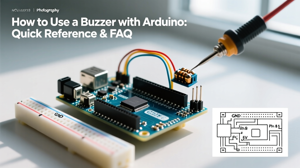
Understanding how to use a buzzer with Arduino starts with identifying the hardware you have on your workbench. Makers generally encounter two types of 5V buzzers in starter kits: active and passive. Confusing the two is the number one cause of 'clicking' or silent failures in beginner audio projects.
| Feature | Active Buzzer (e.g., KY-012) | Passive Buzzer (e.g., KY-006) |
|---|---|---|
| Internal Oscillator | Yes (Built-in) | No (Requires AC/PWM signal) |
| Control Method | digitalWrite(HIGH/LOW) |
tone(pin, freq, duration) |
| Frequency Control | Fixed (Usually ~2.7 kHz) | Variable (31 Hz to 65 kHz) |
| Can Play Melodies? | No (Single pitch only) | Yes |
| Average Cost (2026) | ~$1.50 USD | ~$1.20 USD |
Visual Identification Tip: Turn the buzzer upside down. If the PCB is completely sealed with black epoxy or green solder mask, it is likely an active buzzer. If you can see the exposed copper traces and a bare piezo element or electromagnetic coil, it is passive.
Hardware & Wiring FAQs
Can I wire a buzzer directly to an Arduino digital pin?
While many basic tutorials show a direct connection from a digital pin to a small piezo buzzer, this is technically a bad habit. The ATmega328P microcontroller (found on the Arduino Uno and Nano) has an absolute maximum current rating of 40mA per I/O pin, but the recommended safe operating limit is 20mA.
Most standard 5V electromagnetic buzzers (like the TMB12A05) draw between 30mA and 40mA. Driving them directly will degrade or permanently fry the microcontroller's I/O port over time. Small piezo buzzers draw significantly less current (often under 10mA), making direct connection safer, but using a transistor is the professional standard.
- The Safe Approach: Use an NPN transistor like the 2N2222 or BC547. Connect the Arduino pin to the transistor's Base via a 1kΩ resistor. Connect the Emitter to GND, and the Collector to the negative terminal of the buzzer. Connect the positive terminal to the 5V rail.
Do I need a flyback diode across the buzzer terminals?
It depends on the internal physics of your component. If you are using an electromagnetic buzzer (which uses a physical coil and diaphragm), you absolutely must place a flyback diode (like a 1N4148 or 1N4007) in reverse bias across the terminals (cathode to 5V, anode to the transistor collector). When the coil de-energizes, it generates a reverse voltage spike that can destroy your switching transistor. If you are using a piezoelectric buzzer, it acts as a capacitor, not an inductor, and a flyback diode is not strictly necessary, though a parallel resistor (e.g., 10kΩ) is sometimes used to discharge the piezo element quickly for crisper audio stopping.
Programming & Code FAQs
How do I use the tone() function correctly for maximum volume?
The Arduino tone() function generates a square wave of the specified frequency on a pin. The syntax is tone(pin, frequency, duration). However, simply passing random frequencies will result in quiet, muddy audio.
Piezo buzzers have a specific resonant frequency—usually printed on the datasheet or the side of the component casing (commonly 2.7 kHz, 3.2 kHz, or 4.0 kHz). When you drive the piezo element at its exact resonant frequency, the mechanical vibrations amplify, yielding the maximum Sound Pressure Level (SPL), often peaking around 85dB at 10cm. Driving that same 4.0 kHz piezo at 500 Hz will result in a faint, barely audible hum. Always check your component's datasheet for the 'Resonant Frequency' spec and center your melody notes around that value when possible.
Why is my buzzer breaking my PWM LEDs or Servos?
This is a classic hardware timer conflict. On the Arduino Uno (ATmega328P), the tone() function relies on the microcontroller's hardware Timer 2 to generate the square wave without blocking the main loop(). Unfortunately, Timer 2 is also responsible for handling hardware PWM on Digital Pins 3 and 11.
If you are running tone() on a passive buzzer while simultaneously trying to fade an LED using analogWrite() on Pin 3 or Pin 11, the PWM signal will fail or behave erratically. To resolve this, move your PWM LEDs to Pins 5, 6, 9, or 10 (which use Timer 0 and Timer 1), or move your buzzer logic to a dedicated library that uses software-based timers, though hardware timers are always preferred for audio stability.
Troubleshooting & Edge Cases
Why is my buzzer just clicking instead of playing a tone?
A rapid clicking sound usually indicates a mismatch between your hardware type and your software logic:
- You are using an Active Buzzer with tone(): The active buzzer's internal oscillator is fighting the Arduino's square wave, resulting in a stuttering click. Switch your code to use
digitalWrite(pin, HIGH), delay, anddigitalWrite(pin, LOW). - You are using a Passive Buzzer with digitalWrite(): A passive buzzer requires rapid oscillation to move the diaphragm. A single
digitalWrite(HIGH)will only pull the diaphragm once, creating a single physical 'click'. Switch to thetone()function.
How can I make my piezo buzzer significantly louder?
If you are building an alarm or outdoor notification system, a standard 5V single-ended drive might not provide enough acoustic output. According to audio engineering principles for piezos, volume is dictated by the peak-to-peak voltage swing across the element.
By wiring the piezo buzzer between two Arduino pins and driving them with inverted square waves (Pin A goes HIGH while Pin B goes LOW, and vice versa), you effectively double the voltage swing from 5V peak-to-peak to 10V peak-to-peak. This yields a massive increase in decibel output. For even greater volume, professional designs use an H-Bridge motor driver (like the L293D or TI DRV8833) powered by a 12V external supply, allowing you to drive the piezo element with a 24V peak-to-peak swing safely.
Why does my melody sound distorted or 'warbled'?
Distortion in Arduino melodies is rarely a speaker issue; it is almost always a timing issue in your code. If you are using delay() between notes without properly calling noTone(), the frequencies will overlap or slide into one another. Furthermore, failing to include a brief 'rest' (a period of silence) between notes makes the audio sound like a continuous, sliding siren rather than distinct musical notes.
Pro-Tip for Clean Melodies: Always insert a rest gap equal to at least 10% to 20% of your note duration. For example, if a note plays for 400ms, callnoTone(pin)and delay for an additional 50ms before triggering the nexttone()command. This creates the acoustic 'attack and decay' necessary for the human ear to separate distinct pitches.
Component Quick-Buy Guide (2026)
If you are sourcing components for a production run or a permanent installation, avoid the cheap, unshielded bare-disc piezos found in basic starter kits. Look for enclosed, PCB-mounted modules with integrated resonance chambers. The TDK AST1240MLTRQ is an industry-standard surface-mount electromagnetic transducer that provides excellent SPL at 4.0 kHz, while the CUI Devices CPE-142 series offers robust through-hole piezo options with built-in driver circuits, completely eliminating the need for external transistors or AC signal generation on your microcontroller.
For deeper experimentation with microcontroller audio synthesis, reference the SparkFun Inventor's Guide to Buzzers to explore how to map analog sensor inputs directly to frequency arrays for real-time theremin-style instruments.