
The WS2812B Arduino Compatibility Bottleneck: 5V vs 3.3V Logic
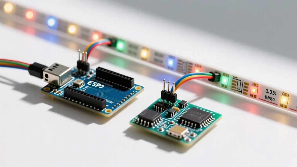
The WS2812B addressable LED (commonly known by the Adafruit trademark 'NeoPixel') remains a staple in DIY electronics. However, as the maker ecosystem has shifted heavily toward 3.3V microcontrollers like the ESP32 and Raspberry Pi Pico, a massive compatibility trap has emerged: logic level mismatch.
According to the official Worldsemi WS2812B datasheet, the high-level input voltage ($V_{IH}$) on the DIN pin must be at least $0.7 \times V_{DD}$. If you power the LED strip with a standard 5V supply, the DIN pin requires a minimum of 3.5V to reliably register a logic HIGH. A 3.3V Arduino or ESP32 outputs exactly 3.3V. While some batches of WS2812B LEDs might 'tolerate' 3.3V data lines in ideal conditions, doing so violates the silicon specifications, leading to erratic flickering, color shifting, or complete signal dropout, especially over longer data runs.
Microcontroller Board Compatibility Matrix
Not all 'Arduino-compatible' boards are created equal when driving 1-wire addressable LEDs. Below is a definitive compatibility guide for the most popular development boards used in 2026.
| Development Board | Logic Level | Direct Connect? | Required Hardware | Best Library |
|---|---|---|---|---|
| Arduino Uno R3 / Mega 2560 | 5V | Yes | 470Ω series resistor on DIN | Adafruit NeoPixel |
| Arduino Nano 33 IoT / BLE | 3.3V | No | SN74AHCT125 Level Shifter | FastLED |
| ESP32 DevKit V1 (Standard) | 3.3V | No | Level Shifter + DMA Pin Selection | FastLED (ESP32 RMT) |
| Raspberry Pi Pico (RP2040) | 3.3V | No | Level Shifter + PIO State Machine | FastLED / Pico-PIO-USB |
Power Delivery: The 60mA Reality Check
A frequent point of failure in WS2812B Arduino projects is attempting to power the LEDs directly from the microcontroller's 5V pin. Each WS2812B LED draws approximately 60mA at full white (all three RGB channels at maximum).
- 10 LEDs: 600mA (Exceeds standard Arduino Uno USB port limits, risking polyfuse tripping).
- 50 LEDs: 3.0A (Requires a dedicated external power supply).
- 144 LEDs (1m strip): 8.64A (Requires heavy-gauge wiring and multiple power injection points).
Expert Rule of Thumb: Never draw more than 300mA through an Arduino's onboard 5V trace. For any WS2812B project exceeding 5 LEDs, use a dedicated 5V switching power supply (like a Mean Well LRS-35-5) and wire the power directly to the LED strip's VCC and GND pads, bypassing the microcontroller's power pins entirely.
For deep-dive power calculations and voltage drop mitigation, the Adafruit NeoPixel Überguide remains the industry-standard reference for calculating wire gauge and injection intervals.
Choosing the Right Logic Level Shifter
If you are using a 3.3V board, you must translate the 3.3V data signal to 5V. However, not all level shifters are compatible with the WS2812B's high-speed data protocol, which operates between 800 kHz and 2.2 MHz depending on the specific LED variant (e.g., the newer WS2812C-2020 mini LEDs).
1. The Gold Standard: SN74AHCT125
The Texas Instruments SN74AHCT125 is a quad bus buffer gate. By powering the chip's VCC with 5V and feeding the 3.3V Arduino data line into the input, it outputs a rock-solid 5V signal with propagation delays measured in nanoseconds. At roughly $0.65 per IC in 2026, it is the most reliable solution for WS2812B compatibility.
2. The Bidirectional Trap: BSS138 MOSFET Shifters
Many beginners purchase cheap 'I2C Logic Level Converter' modules based on the BSS138 MOSFET. Do not use these for WS2812B LEDs. I2C operates at a sluggish 100 kHz to 400 kHz and relies on pull-up resistors. The gate capacitance of the BSS138, combined with the slow rise times of pull-up resistors, will severely distort the tight microsecond timing pulses required by the WS2812B protocol, resulting in corrupted color data.
Library Nuances: FastLED vs. Adafruit NeoPixel
When configuring your Arduino IDE, library selection dictates hardware compatibility. Both FastLED and Adafruit NeoPixel are excellent, but they handle microcontroller architecture differently.
ESP32 DMA and Pin Conflicts
The ESP32 uses the Remote Control (RMT) peripheral or DMA to generate WS2812B timing pulses without blocking the main CPU. However, you must avoid specific GPIO pins:
- GPIO 6 to 11: Connected to the integrated SPI flash. Using these will cause immediate boot loops.
- GPIO 2: Often tied to the boot mode strapping pin; driving it HIGH during boot can prevent the ESP32 from entering flash mode.
- GPIO 16/17 (on some variants): Reserved for PSRAM on WROVER modules.
Safe ESP32 Pins for WS2812B: GPIO 4, 5, 12, 13, 14, 15, 18, 19, 21, 22, 23, 25, 26, 27, 32, 33.
Raspberry Pi Pico (RP2040) PIO Advantage
The RP2040's Programmable I/O (PIO) state machines are perfectly suited for the WS2812B protocol. Unlike the ATmega328P (Arduino Uno) which must disable all interrupts to bit-bang the LED data (causing issues with WiFi or serial communication), the Pico's PIO handles the 800kHz signal in the background. Ensure you are using FastLED v3.7 or newer, which includes native RP2040 PIO support.
Step-by-Step Bulletproof Wiring Protocol
To guarantee 100% compatibility and protect your hardware, follow this exact wiring sequence for any WS2812B Arduino project:
- The Capacitor: Solder a 1000µF, 6.3V (or higher) electrolytic capacitor directly across the 5V and GND power rails at the start of the LED strip. This buffers sudden current spikes when all LEDs turn white simultaneously, preventing brownout resets on your Arduino.
- The Level Shifter (3.3V boards only): Wire the 3.3V data output from your MCU to the input of the SN74AHCT125. Wire the 5V VCC to the shifter's power pin. Take the 5V output from the shifter to the LED strip.
- The Series Resistor: Place a 300Ω to 470Ω resistor on the 5V data line, as close to the LED strip's DIN pad as possible. This prevents high-frequency ringing and protects the first LED's data input from voltage spikes.
- Common Ground: You must connect the GND of your external 5V power supply to the GND pin of your Arduino. Without a shared ground reference, the data signal will float, and the LEDs will not respond.
Final Troubleshooting Checklist
If your WS2812B strip is only lighting up the first LED, or showing random colors, check these three edge cases:
- RGB vs GRB Color Order: Standard WS2812B chips use a GRB (Green-Red-Blue) color order. If your code is sending RGB, your red and green commands will be swapped. Initialize your FastLED strip with
GRBinstead ofRGB. - Data Direction: WS2812B strips are directional. Ensure your DIN (Data In) is connected to the Arduino, not DOUT. Look for the arrows printed on the LED strip's PCB—they must point away from the Arduino.
- Voltage Drop: If the LEDs at the end of a 2-meter strip look yellow or dim, you are experiencing voltage drop on the 5V rail. Inject 5V power at both the beginning and the end of the strip using 18 AWG silicone wire.