
Quick Reference: Control LED with Photoresistor Arduino
Building a light-activated circuit is a foundational milestone in embedded electronics. When you control LED with photoresistor Arduino setups, you are bridging the gap between analog environmental sensing and digital logic. Whether you are building an automated night-light, a security tripwire, or a solar tracker, understanding the nuances of Light Dependent Resistors (LDRs) is critical. This 2026 quick reference guide cuts through the fluff, providing exact component specifications, wiring matrices, and engineering solutions to common edge cases like dusk-flicker and ADC noise.
Bill of Materials (BOM) & Component Specs
Selecting the right components prevents voltage sag and ensures reliable analog-to-digital conversion. Below is the recommended BOM for a standard 5V Arduino Uno R3 or R4 Minima setup.
| Component | Model / Value | 2026 Est. Price | Engineering Purpose |
|---|---|---|---|
| Photoresistor (LDR) | GL5528 | $0.12 | 10kΩ-20kΩ at 10 lux. Dark resistance >1MΩ. |
| Pull-Down Resistor | 10kΩ (1/4W Carbon) | $0.02 | Forms voltage divider; matches GL5528 mid-point. |
| Standard LED | 5mm Diffused (Any Color) | $0.05 | Visual indicator output. |
| Current Limiter | 220Ω or 330Ω Resistor | $0.02 | Limits LED current to ~15mA (safe for GPIO). |
| Decoupling Capacitor | 100nF (0.1µF) Ceramic | $0.03 | Filters high-frequency noise on the analog pin. |
Exact Wiring Matrix
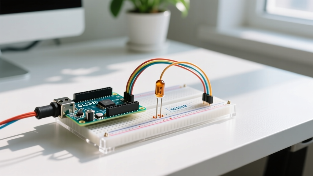
Proper grounding and power routing are essential. The LDR does not have polarity, but the voltage divider junction must be wired precisely.
- 5V Pin: Connect to LDR Leg 1.
- GND Pin: Connect to 10kΩ Resistor Leg 2 AND Capacitor Leg 2 AND LED Cathode (short leg).
- Analog Pin A0: Connect to the junction of LDR Leg 2, 10kΩ Resistor Leg 1, and Capacitor Leg 1.
- Digital Pin D8: Connect to 220Ω Resistor Leg 1. Connect 220Ω Resistor Leg 2 to LED Anode (long leg).
The Core Concept: The Voltage Divider
Microcontrollers cannot read resistance directly; they only read voltage. To utilize a voltage divider, we pair the variable resistance of the GL5528 with a fixed 10kΩ resistor. The Arduino's 10-bit ADC (Analog-to-Digital Converter) maps the 0-5V range to integer values between 0 and 1023.
The Math: Vout = 5V × [10kΩ / (R_LDR + 10kΩ)]
Daylight (approx 100 lux): GL5528 drops to ~2kΩ. Vout = 5 × (10 / 12) = 4.16V. ADC reads ~852.
Darkness (approx 0 lux): GL5528 spikes to ~200kΩ. Vout = 5 × (10 / 210) = 0.23V. ADC reads ~48.
This inverse relationship means lower analog values correspond to darker environments when the LDR is placed on the high-side (connected to 5V).
Frequently Asked Questions (FAQ)
1. Why does my LED flicker rapidly at dusk or dawn?
This is the most common issue when users attempt to control LED with photoresistor Arduino circuits using a simple if (light < 500) statement. At twilight, ambient light hovers exactly around your threshold. Clouds passing by or shadows from trees cause the ADC value to rapidly cross the threshold back and forth, resulting in a strobe effect.
The Engineering Fix: Implement software hysteresis (a Schmitt trigger). By creating two separate thresholds—one for turning ON and a slightly different one for turning OFF—you create a 'dead zone' that prevents rapid toggling.
// Hysteresis Implementation
const int LDR_PIN = A0;
const int LED_PIN = 8;
int lightLevel;
bool ledState = false;

void setup() {
  pinMode(LED_PIN, OUTPUT);
}

void loop() {
  lightLevel = analogRead(LDR_PIN);

  // Turn ON when it gets dark (Value drops below 400)
  if (lightLevel < 400 && !ledState) {
    digitalWrite(LED_PIN, HIGH);
    ledState = true;
  }
  // Turn OFF only when it gets significantly brighter (Value rises above 480)
  else if (lightLevel > 480 && ledState) {
    digitalWrite(LED_PIN, LOW);
    ledState = false;
  }
  delay(100); // Debounce delay
}
2. Can I skip the analog pin and wire the LDR directly to a digital pin?
Technically, you can wire the voltage divider junction to a digital pin (e.g., D2), but it is highly discouraged for precision applications. According to the Arduino analog and digital I/O specifications, the ATmega328P microcontroller defines logic LOW (VIL) as anything below 0.3 VCC (1.5V) and logic HIGH (VIH) as anything above 0.6 VCC (3.0V).
The gap between 1.5V and 3.0V is an undefined transition zone. As the sun sets, the voltage will slowly drift through this 1.5V window, causing the digital pin to read unpredictable HIGH/LOW states. If you strictly require a digital signal (to trigger an interrupt, for example), bypass the Arduino's internal logic and use an external LM393 Dual Comparator IC (approx. $1.50 for a 2-pack). The LM393 compares the LDR voltage against a potentiometer-set reference voltage and outputs a clean, sharp 5V or 0V square wave.
3. My analogRead() values are jittering by ±15 points. Is my ADC broken?
No, your ADC is likely functioning perfectly. The 10-bit ADC on standard Arduino boards is highly sensitive to electromagnetic interference (EMI), USB power rail noise, and breadboard parasitic capacitance. A jitter of 10-20 points is entirely normal in raw, unfiltered readings.
Hardware Fix: This is why the 100nF ceramic capacitor is included in the BOM. Placing this capacitor directly across the A0 pin and GND creates a low-pass filter, smoothing out high-frequency transient noise before it reaches the ADC sample-and-hold circuit.
Software Fix: Implement oversampling. Take 16 rapid readings, sum them, and divide by 16. This mathematical averaging dramatically reduces standard deviation and yields a rock-solid baseline value.
Advanced Troubleshooting Matrix
When your circuit fails to behave as expected, use this diagnostic matrix to isolate the fault.
| Symptom | Root Cause | Engineering Fix |
|---|---|---|
| ADC reads a constant 1023 regardless of light. | Floating Analog Pin or LDR wired directly to 5V without pull-down. | Verify the 10kΩ pull-down resistor is connected to GND. Check breadboard continuity. |
| ADC reads a constant 0 regardless of light. | LDR and Pull-down resistor positions are swapped. | Swap the LDR and 10kΩ resistor. (Note: Swapping them inverts the logic; darkness will now yield high values). |
| LED glows dimly but never fully turns off. | GPIO pin configured as INPUT instead of OUTPUT, or PWM leakage. | Ensure pinMode(LED_PIN, OUTPUT); is in the setup() block. |
| Circuit triggers at night but also triggers when I wave my hand over it during the day. | Threshold set too high; overly sensitive to minor shadow transients. | Use the Arduino IDE Serial Plotter to map your specific room's lux profile and adjust hysteresis thresholds accordingly. |
Final Calibration Tips for Maker Projects
As of 2026, the maker ecosystem offers incredible tools for tuning analog sensors. Before soldering your final PCB or permanent perfboard layout, always utilize the Arduino IDE Serial Plotter (found under Tools > Serial Plotter). By printing your raw analogRead() values to the plotter, you can visually graph the exact voltage curve of your room as the sun sets.
Furthermore, consider the physical housing of your photoresistor. Optoelectronic devices are highly directional. If you 3D print an enclosure for your night-light, ensure the LDR is seated in a shallow, matte-black bezel to prevent internal LED light bleed from creating a false 'daylight' reading, which would result in an endless feedback loop of the light turning itself off and on.