
Arduino port manipulation is the practice of directly writing to microcontroller hardware registers to control I/O pins, bypassing the overhead of the standard digitalWrite() function. This guide is designed for embedded systems engineers, robotics developers, and advanced hobbyists who require deterministic, high-speed I/O operations. By manipulating the Data Direction Register (DDRx), Port Register (PORTx), and Pin Register (PINx), developers can reduce pin-toggle execution time from 5.2 microseconds to just 0.125 microseconds on a 16 MHz Microchip ATmega328P.
- Direct port manipulation reduces I/O latency by over 97% compared to standard Arduino abstraction functions.
- AVR hardware registers (DDRx, PORTx, PINx) map directly to physical 8-bit pin groups.
- Bitwise operators allow isolated pin control without disrupting adjacent I/O states on the same port.
What is Arduino Port Manipulation?
Port manipulation involves writing directly to the memory addresses that control the physical pins of a microcontroller. Instead of relying on software abstraction layers, you interact with the silicon hardware directly.
Port Register: A dedicated 8-bit memory address inside the microcontroller that directly controls the physical state, direction, or input reading of a specific group of eight I/O pins.
Bitwise Operation: A programming technique that manipulates individual bits within a byte using logical operators like AND, OR, and XOR to change specific pin states without affecting neighboring pins.
The Speed Bottleneck of digitalWrite()
The standard digitalWrite() function prioritizes ease of use over execution speed. When you call this function, the microcontroller must perform several background tasks before toggling the pin.
First, the function checks if the pin is assigned to a Pulse Width Modulation (PWM) timer and disables it if necessary. Next, it translates the friendly Arduino pin number into the corresponding AVR port and bit mask. According to the Arduino Official Language Reference, this abstraction layer adds significant computational overhead.
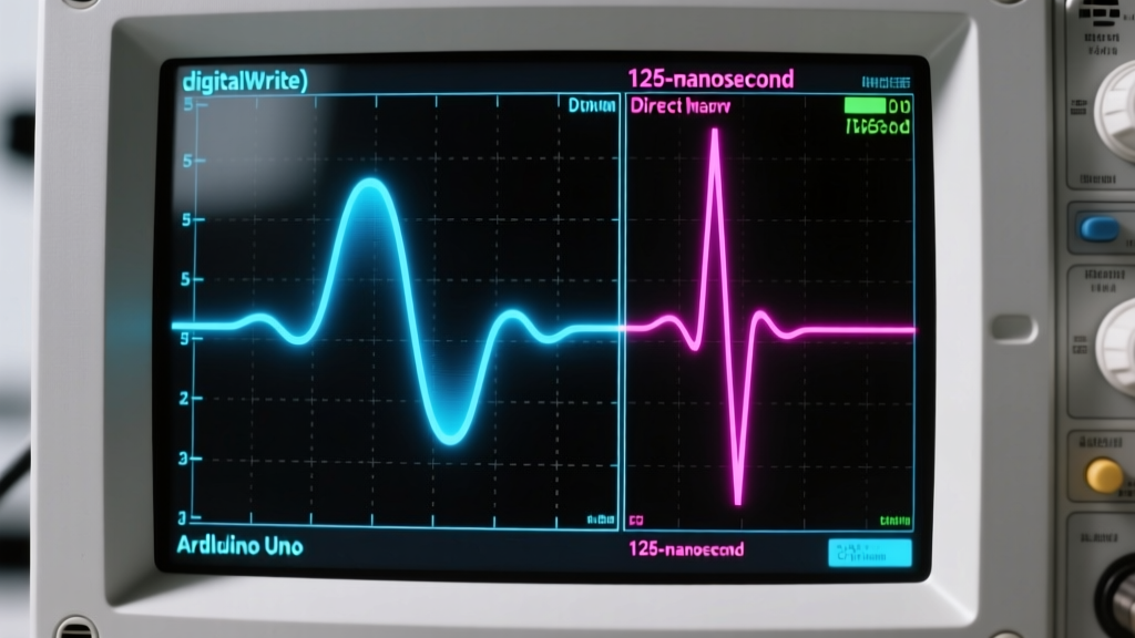
On an Arduino Uno running at 16 MHz, a single digitalWrite() call takes approximately 5.2 microseconds. While this is sufficient for blinking LEDs, it severely limits applications requiring high-frequency signal generation or precise time-division multiplexing.
How to Use AVR Port Registers
The Microchip ATmega328P groups its I/O pins into three main ports: Port B, Port C, and Port D. Each port is controlled by three specific 8-bit registers.
Configuring Pin Directions (DDRx)
The Data Direction Register (DDRx) dictates whether a pin acts as an input or an output. Writing a '1' to a specific bit configures that pin as an output, while writing a '0' configures it as an input.
For example, setting DDRD = B11111100; configures pins 2 through 7 on Port D as outputs, while leaving pins 0 and 1 (the hardware serial RX/TX lines) as inputs. This protects your serial communication from accidental overwrites.
Writing Output States (PORTx)
The PORTx register controls the actual logic level of the pins configured as outputs. Setting a bit high outputs 5 volts, while setting it low outputs 0 volts.
Using bitwise OR operations allows you to set a pin high without altering the rest of the port. The command PORTD |= (1 << 3); sets pin 3 high while leaving all other Port D pins in their current states.
Reading Input States (PINx)
The PINx register reads the current physical voltage level present on the port pins. Unlike PORTx, which holds the commanded state, PINx reflects the real-world electrical state.
To check if pin 4 is receiving a high signal, you use a bitwise AND operation: if (PIND & (1 << 4)). This isolates the fourth bit for evaluation without reading the entire byte as a single integer.
Performance Comparison and Decision Framework
Choosing between standard functions and direct register access depends on your project constraints. Use the following decision framework to determine the optimal approach for your embedded system.
| Metric | digitalWrite() | Direct Port Manipulation |
|---|---|---|
| Execution Time | 5.2 microseconds | 0.125 microseconds (2 clock cycles) |
| Code Readability | High (Beginner friendly) | Low (Requires datasheet reference) |
| Portability | Universal across all Arduino boards | Hardware-specific (AVR only) |
| Memory Footprint | Larger compiled binary size | Minimal instruction overhead |
| Current Limit | 40 milliamperes per pin | 40 milliamperes per pin (Hardware limit) |
Direct port manipulation is mandatory when driving multiplexed LED matrices, implementing software-based serial protocols, or reading high-speed rotary encoders. Standard functions remain superior for basic sensor polling and actuator control where timing tolerances exceed 10 microseconds.
Frequently Asked Questions
How much faster is direct port manipulation than digitalWrite?
Direct port manipulation is approximately 41 times faster than the standard digitalWrite() function. A direct register write completes in 2 clock cycles (0.125 microseconds at 16 MHz), whereas digitalWrite() requires over 80 clock cycles to execute its internal mapping and safety checks.
How do you read a full port in Arduino?
You read a full port by querying the PINx register. Assigning a variable to PINB captures the simultaneous state of all 8 bits on Port B. This parallel reading is essential for capturing high-speed data buses where sequential pin reading would introduce skew.
What are the hardware risks of port manipulation?
The primary risk is accidentally overwriting critical system pins. For example, altering Port D without preserving bits 0 and 1 will disable the hardware UART serial communication. Always use bitwise masking to protect essential pins when modifying register states.
Summary and Next Steps
Arduino port manipulation solves the inherent latency issues of standard I/O functions by providing direct, cycle-accurate access to the Microchip ATmega328P hardware registers. By mastering DDRx, PORTx, and PINx, you unlock the ability to write highly optimized, deterministic embedded code that operates at the physical limits of the 16 MHz clock speed.
Your next step is to open your development environment, identify the most time-critical I/O loop in your current project, and replace the standard pin commands with bitwise register operations. Verify the performance gain by measuring the pin toggle frequency with an oscilloscope or a high-speed logic analyzer.