
Why You Need OpenOCD in the Arduino IDE
If you are transitioning from blinking LEDs to building complex state machines or RTOS-based firmware, relying solely on Serial.print() for debugging is a massive bottleneck. Hardware debugging allows you to set breakpoints, inspect registers, and step through C++ code line-by-line. At the heart of this hardware debugging pipeline is OpenOCD (Open On-Chip Debugger).
While the modern Arduino IDE 2.x includes native debugging support via the Cortex-Debug extension, it relies on OpenOCD to translate GDB (GNU Debugger) commands into the low-level SWD or JTAG signals your debug probe (like an ST-Link or J-Link) understands. For official boards like the Arduino Nano 33 BLE or Portenta H7, OpenOCD is installed automatically. However, if you are working with third-party cores (like STM32duino, custom RP2040 boards, or bare-metal ESP32 setups), you must manually install and configure OpenOCD into the Arduino IDE environment.
Prerequisites for Hardware Debugging
Before diving into the directory structures and configuration files, ensure your workbench is equipped with the following:
- Software: Arduino IDE 2.3.x or newer (Legacy 1.8.x does not support native GUI debugging).
- Debug Probe: ST-Link V2 (clone or genuine), Segger J-Link EDU, or a CMSIS-DAP compatible probe.
- Target MCU: An ARM Cortex-M microcontroller (e.g., STM32F103C8T6, SAMD21) or an ESP32 with JTAG pins exposed.
- Wiring: Female-to-female jumper wires for SWD connections.
The xPack OpenOCD Advantage
When learning how to install OpenOCD into Arduino IDE, you will quickly discover that compiling upstream OpenOCD from source is a dependency nightmare for beginners. Instead, the industry standard for embedded IDE integration is the xPack OpenOCD project. Maintained by Liviu Ionescu, xPack provides pre-compiled, standalone binaries for Windows, macOS, and Linux that are specifically patched to work seamlessly with Eclipse, PlatformIO, and the Arduino IDE's underlying Cortex-Debug architecture.
Pro Tip: Always use the xPack OpenOCD builds rather than the default MSYS2 or Homebrew OpenOCD packages. The xPack versions include vital RTOS awareness plugins (FreeRTOS, Zephyr) that the vanilla upstream builds often omit.
Step-by-Step: Installing OpenOCD for Custom Cores
Step 1: Locate Your Arduino15 Packages Directory
The Arduino IDE stores third-party board manager cores and tools in a hidden system directory. You need to place the OpenOCD binary here so the IDE's build system can find it.
- Windows:
C:\Users\[YourUsername]\AppData\Local\Arduino15\packages\ - macOS:
/Users/[YourUsername]/Library/Arduino15/packages/ - Linux:
/home/[YourUsername]/.arduino15/packages/
Navigate to the specific core folder you are using. For example, if you are using STM32duino, the path will look like: .../packages/STM32/hardware/stm32/2.6.0/.
Step 2: Download and Extract xPack OpenOCD
Head over to the xPack OpenOCD GitHub Releases page and download the latest stable archive for your operating system (e.g., xpack-openocd-0.12.0-4-win32-x64.zip).
Extract the contents of this archive. Inside, you will find a folder named bin containing the openocd executable, and a folder named scripts containing the target and interface configuration files.
Step 3: Structure the Tool Directory
Arduino's build system expects tools to follow a strict versioned directory hierarchy. Inside your core's base directory (or a shared tools directory), create the following folder structure:
tools/openocd/0.12.0-4/
Move the extracted bin, scripts, and license folders directly into the 0.12.0-4 version folder. Your final path to the executable should look like this on Windows:
C:\Users\User\AppData\Local\Arduino15\packages\STM32\tools\openocd\0.12.0-4\bin\openocd.exe
Step 4: Modify platform.txt to Recognize OpenOCD
The Arduino IDE uses platform.txt to define toolchain paths. Open the platform.txt file located in your core's root directory using a text editor like VS Code or Notepad++.
Search for the OpenOCD tool definitions. If they are missing or pointing to a wrong version, add or modify these lines:
tools.openocd.path={runtime.tools.openocd.path}
tools.openocd.cmd=bin/openocd
tools.openocd.cmd.windows=bin/openocd.exe
Save the file and completely restart the Arduino IDE. The IDE will now index the new tool and make it available to the debugger.
Hardware Wiring Matrix: SWD Pinouts
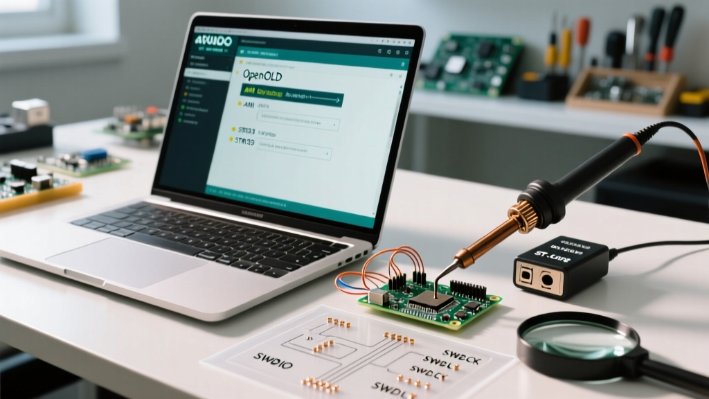
OpenOCD cannot communicate with your microcontroller if the physical layer is incorrect. Most beginner ARM debugging setups utilize the Serial Wire Debug (SWD) protocol, which requires only four connections. Refer to the table below for standard wiring between your debug probe and target MCU.
| Probe Pin (ST-Link/J-Link) | Target MCU Pin | Function & Electrical Notes |
|---|---|---|
| 3.3V (VCC) | 3.3V (VDD) | Powers the optocouplers/level shifters on the probe. Do not connect to 5V on 3.3V logic boards. |
| GND | GND | Common ground reference. Essential for signal integrity. |
| SWDIO (TMS) | SWDIO (PA13 on STM32) | Serial Wire Debug Input/Output. Bi-directional data line. |
| SWCLK (TCK) | SWCLK (PA14 on STM32) | Serial Wire Debug Clock. Driven by the probe. |
| NRST (Optional) | NRST | Hardware reset line. Required for 'connect under reset' debugging. |
Troubleshooting Common OpenOCD Errors in Arduino IDE
Even with a perfect software installation, hardware debugging often fails at the physical or permission layer. Here is how to resolve the most common OpenOCD errors encountered by beginners.
1. Error: libusb_open() failed with LIBUSB_ERROR_ACCESS
The Cause: This is exclusively a Linux (Ubuntu/Debian/Fedora) issue. The operating system's default USB permissions block non-root users from accessing the ST-Link or J-Link hardware.
The Fix: You must create a custom udev rule. Open your terminal and create a new file:
sudo nano /etc/udev/rules.d/99-stlink.rulesPaste the following rule to grant read/write access to the ST-Link V2 (Vendor ID 0483, Product ID 3748):
SUBSYSTEM=="usb", ATTR{idVendor}=="0483", ATTR{idProduct}=="3748", MODE="0666"Reload the rules with sudo udevadm control --reload-rules and physically unplug and replug your debug probe.
2. Error: unable to open ftdi device / Init mode failed
The Cause: OpenOCD is attempting to use the wrong interface configuration file, or your wiring is missing the GND connection, causing the clock signal to float.
The Fix: Verify your GND connection first. If the wiring is correct, check the openocd.cfg file generated by the Arduino IDE in your sketch's build folder. Ensure it includes the correct interface line, such as source [find interface/stlink.cfg]. If you are using a clone ST-Link that uses a different chip, you may need to modify the interface script to use hla_serial or switch to the cmsis-dap interface.
3. GDB Server Crashing on Breakpoint
The Cause: Flash memory write protection is enabled on the STM32, or the read-out protection (RDP) level is set to 1 or 2.
The Fix: Use the official STM32CubeProgrammer utility to connect to the chip via UR (Under Reset) and perform a full chip erase to clear the RDP bits. OpenOCD cannot overwrite protected flash sectors to set software breakpoints.
Expanding Your Debugging Capabilities
Mastering how to install OpenOCD into Arduino IDE unlocks professional-grade firmware development workflows. Once configured, you can utilize the Arduino IDE 2.x debugger to inspect FreeRTOS task stacks, monitor peripheral registers in real-time, and catch hard faults before they trigger a watchdog reset. For further reading on configuring GDB scripts and advanced RTOS debugging, consult the official OpenOCD User Manual and the Arduino IDE 2 Debugger Documentation.
By moving beyond serial printing and embracing SWD hardware debugging, you will drastically reduce your development cycle time and produce significantly more robust embedded systems.