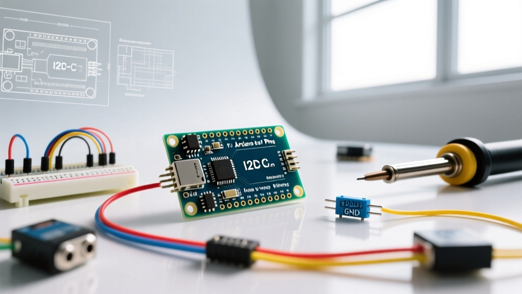

Evaluating the ATmega328P for Modern Sensor Arrays
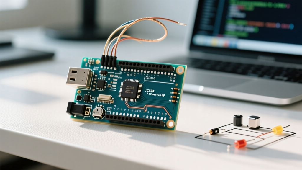
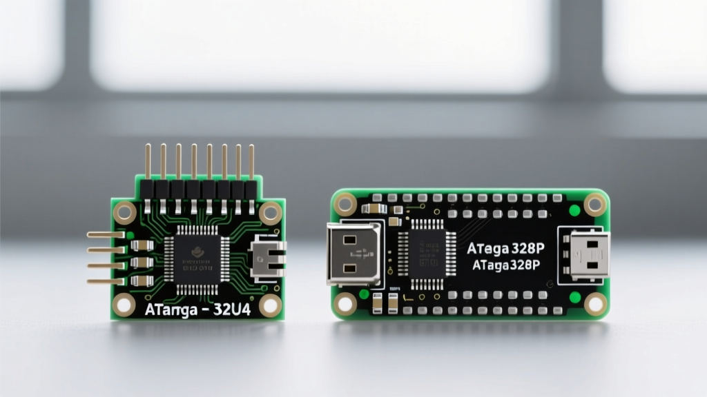
When designing embedded systems that rely on multi-drop sensor networks, evaluating the i2c arduino nano pins is a critical first step. The Arduino Nano, powered by the ATmega328P microcontroller, remains a staple in DIY electronics due to its compact breadboard-friendly footprint and low cost (typically $3.50 to $6.00 for CH340G-based clones in 2026). However, as modern I2C sensors like the Bosch BME688 or Sensirion SCD41 demand stricter electrical tolerances, the Nano’s native I2C implementation presents specific engineering constraints. This project suitability analysis breaks down the hardware realities, bus capacitance limits, and logic-level pitfalls of using the Nano for I2C communication.
Mapping the I2C Arduino Nano Pins: A4 and A5
On the standard Arduino Nano V3 layout, the I2C bus is hardcoded to specific analog pins:
- SDA (Serial Data): Pin A4
- SCL (Serial Clock): Pin A5
Unlike newer development boards that feature dedicated, separate pins for I2C alongside analog inputs, the Nano multiplexes these functions. This means if your project requires reading analog signals from A4 or A5 while simultaneously running an I2C bus, you will face a hardware conflict. For projects requiring more than four analog inputs alongside I2C, the Nano's pinout becomes a bottleneck, necessitating an external multiplexer like the TCA9548A or an upgrade to an Arduino Mega 2560.
The 5V vs 3.3V Logic Level Trap
The most frequent point of failure in Nano-based I2C projects is voltage mismatch. The ATmega328P on the Nano operates at 5V logic. Consequently, the SDA and SCL pins output 5V HIGH signals. However, nearly all high-performance environmental, time-of-flight, and gas sensors released in recent years operate strictly at 3.3V.
Critical Warning: Connecting a 3.3V-only sensor (like the VL53L1X or BME280) directly to the 5V I2C Arduino Nano pins will likely degrade the sensor's internal silicon over time or cause immediate catastrophic failure, even if the sensor's VIN pin is correctly supplied with 3.3V.
The Solution: You must implement a bi-directional logic level shifter. The most reliable and cost-effective option is a MOSFET-based shifter utilizing the BSS138 N-channel MOSFET (available on breakout boards from SparkFun or Adafruit for roughly $2.95). This safely translates the 5V signals from A4/A5 down to 3.3V for the sensor bus without the signal degradation associated with simple resistor-divider networks.
Project Suitability Matrix: Nano vs. Alternatives
Is the Nano the right board for your specific I2C topology? Use this decision matrix to determine platform suitability based on project parameters.
| Project Parameter | Arduino Nano (ATmega328P) | ESP32-WROOM-32 | Raspberry Pi Pico (RP2040) |
|---|---|---|---|
| Native Logic Voltage | 5V (Requires level shifting for modern sensors) | 3.3V (Native match for modern sensors) | 3.3V (Native match for modern sensors) |
| Hardware I2C Buses | 1 (Fixed to A4/A5) | 2 (I2C0 and I2C1, highly mappable) | 2 (I2C0 and I2C1, highly mappable) |
| Max Bus Devices | ~4 to 6 (Limited by 2KB SRAM and bus capacitance) | 10+ (Ample RAM for large buffers) | 10+ (264KB SRAM handles massive arrays) |
| Clock Stretching Support | Poor (Wire library often times out) | Excellent (Hardware handled) | Excellent (Hardware handled) |
| Best Use Case | Simple, single-sensor 5V-tolerant projects | Complex IoT sensor nodes requiring Wi-Fi/BLE | High-speed data logging with multiple sensors |
Bus Capacitance and the 400pF Hard Limit
The I2C protocol is an open-drain architecture, meaning devices can only pull the line LOW; they rely on external pull-up resistors to bring the line HIGH. According to the official NXP I2C-bus specification (UM10204), the maximum allowable bus capacitance is 400pF for standard (100kHz) and fast (400kHz) modes.
When utilizing the i2c arduino nano pins for distributed sensors, wire capacitance becomes the limiting factor. Standard Cat5e twisted pair cable exhibits approximately 50pF per meter. If you are wiring sensors across a room or inside a vehicle:
- 1 meter of wire: ~50pF
- 5 meters of wire: ~250pF
- Parasitic capacitance per sensor: ~10pF to 15pF
If your total bus capacitance exceeds 400pF, the RC time constant of the pull-up resistor and the bus capacitance will cause the SDA/SCL rising edges to become sluggish. The ATmega328P will misinterpret these slow ramps as logic LOWs, resulting in corrupted data or complete bus lockups. For long-distance Nano projects, you must abandon standard I2C and use an I2C bus extender IC like the P82B96, which converts the signal to a differential voltage for long-haul transmission.
Calculating the Correct Pull-Up Resistors
A common beginner mistake is relying on the ATmega328P's internal pull-up resistors, which are activated via Wire.begin() in some older library versions. The internal pull-ups are typically 20kΩ to 50kΩ—far too weak to overcome bus capacitance at 400kHz. The official Arduino Wire library documentation recommends disabling internal pull-ups and using external resistors.
To calculate the optimal external pull-up resistor, Texas Instruments provides a rigorous framework in their I2C Bus Pull-Up Resistor Calculation application note (SLVA704). As a practical rule of thumb for the Nano's 5V bus:
- 100kHz (Standard Mode): Use 4.7kΩ resistors.
- 400kHz (Fast Mode): Use 2.2kΩ resistors to ensure faster rise times.
- 1MHz (Fast Mode Plus): The ATmega328P hardware does not reliably support FM+ without severe software overhead; avoid this speed on the Nano.
Edge Case: The Clock Stretching Timeout
Clock stretching is a mechanism where a slave device holds the SCL line LOW to force the master to wait while it processes data. Sensors like the Sensirion SCD30 (CO2) or complex OLED displays frequently use this. The hardware I2C peripheral on the ATmega328P, combined with the standard Arduino Wire library, has a notoriously short timeout for clock stretching. If the sensor holds the line LOW for more than a few milliseconds, the Nano's I2C bus will hang indefinitely, requiring a hard reset.
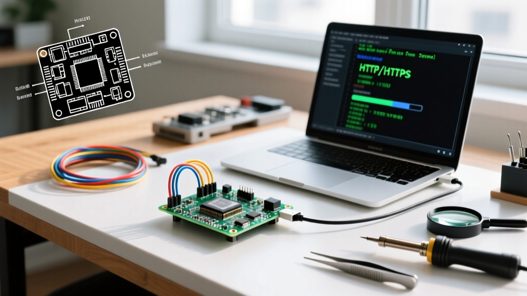
Troubleshooting Step: If your Nano hangs when querying a specific sensor, check the sensor's datasheet for 'clock stretching' requirements. If present, you must either implement a software I2C (bit-banging) library using SoftwareWire on alternative digital pins (e.g., D2 and D3) which allows for customizable timeouts, or migrate your project to an ESP32, which handles clock stretching natively in hardware.
Final Verdict: When to Use the Nano for I2C
The Arduino Nano remains highly suitable for localized, low-complexity I2C projects—such as reading a single 5V-tolerant OLED display or interfacing with legacy 5V EEPROMs. However, for modern 2026 sensor arrays requiring 3.3V logic, long cable runs, or devices that utilize clock stretching, the Nano's hardware limitations introduce unnecessary friction. By understanding the exact electrical boundaries of the A4 and A5 pins, you can accurately scope your bill of materials, ensuring you include the necessary BSS138 level shifters and 2.2kΩ pull-up resistors to guarantee reliable bus communication.