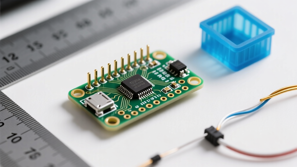

Why the Size of Arduino Nano Dictates Project Architecture
When miniaturizing DIY electronics, the size of Arduino Nano is often the primary constraint driving your mechanical and electrical design. Unlike the bulky Arduino Uno or the ultra-compact surface-mount alternatives, the Nano occupies a highly specific middle ground: it offers the full ATmega328P (or ATmega4809) processing power while maintaining a breadboard-friendly footprint. As of 2026, with the proliferation of compact FPV drones, wearable health monitors, and custom macro-keyboards, understanding the exact dimensional tolerances of the Nano is no longer optional—it is a requirement for successful CAD modeling and PCB integration.
In this deep dive, we break down the precise physical dimensions, hidden spacing metrics, and mechanical edge cases of the Arduino Nano ecosystem, providing actionable data for engineers and makers designing custom enclosures and carrier boards.
Core Physical Dimensions: The Metric & Imperial Breakdown
The official footprint of the classic Arduino Nano is standardized, but component heights can vary based on the specific manufacturer's bill of materials (BOM). Below is the definitive dimensional matrix for a genuine Arduino Nano (ATmega328P variant).
| Parameter | Metric (mm) | Imperial (inches) | Design Notes & Tolerances |
|---|---|---|---|
| PCB Length | 45.0 mm | 1.77 in | Excludes USB port overhang |
| PCB Width | 18.0 mm | 0.71 in | Dictates breadboard compatibility |
| Height (Board Only) | 1.6 mm | 0.063 in | Standard FR4 fiberglass thickness |
| Height (Max Component) | ~12.0 mm | ~0.47 in | Measured to top of male headers |
| Height (Without Headers) | ~4.5 mm | ~0.18 in | Determined by Mini-B USB port |
| Weight (With Headers) | ~7.0 g | 0.25 oz | Critical for micro-drone inertia |
| Weight (Without Headers) | ~5.0 g | 0.18 oz | Header pins account for ~2g |
The USB Port Overhang Factor
A frequent failure mode in novice CAD designs is ignoring the USB connector overhang. The classic genuine Nano utilizes a Mini-B USB receptacle. This metal shielding extends approximately 1.2 mm past the 45 mm PCB edge. If you design an enclosure with an internal length of exactly 45 mm, the USB port will prevent the board from seating flush, potentially bending the connector off the PCB pads. Always allocate a minimum of 47 mm for the internal X-axis cavity.
The 0.6-Inch Breadboard Rule: Header Spacing Explained
The width of the Nano (18 mm) is not arbitrary; it is mathematically derived from standard DIP (Dual In-line Package) spacing. The male pin headers are spaced at standard 0.1-inch (2.54 mm) intervals. Crucially, the distance between the two rows of headers is exactly 0.6 inches (15.24 mm).
Engineering Insight: A standard solderless breadboard features a center divider separating two 5-hole rows. The 0.6-inch span of the Nano perfectly bridges this center divider, leaving exactly one row of 5 holes exposed on either side for jumper wire access. If you are designing a custom perfboard or carrier PCB, locking your header footprints to a 15.24 mm grid spacing is mandatory for ecosystem compatibility.Genuine vs. Clone: Sizing Discrepancies You Must Anticipate
While the official Arduino Store lists the standard dimensions, the 2026 market is flooded with third-party clones that deviate in ways that can ruin mechanical fits. According to the Arduino Nano Official Documentation, the genuine board uses a Mini-B USB port. However, clone manufacturers frequently alter the BOM to reduce costs.
- Micro-USB Clones: Many budget boards replace the Mini-B port with Micro-USB. This reduces the Z-axis height of the connector from ~4.5 mm to ~2.8 mm, and alters the X-axis overhang to nearly 0 mm (flush with the PCB). Enclosures designed for genuine boards will have misaligned USB cutouts.
- USB-C Clones: Modern clones often feature USB-C. The USB-C receptacle is typically 3.2 mm in height and requires a wider lateral cutout (approx. 9.0 mm) compared to the Mini-B (8.5 mm).
- Header Length Variations: Genuine boards ship without headers soldered on. Many clones ship with pre-soldered headers that may be 11.5 mm or 12.5 mm tall, altering your Z-axis clearance by up to 1 mm.
Nano Family Comparison Matrix
The 'Nano' form factor has expanded into a broader family of microcontrollers. If your project requires wireless connectivity or higher processing power, you may need to swap boards. Here is how the physical footprint compares across the modern Nano lineup.
| Board Model | MCU Core | PCB Footprint | Max Z-Height (No Headers) | Key Mechanical Difference |
|---|---|---|---|---|
| Classic Nano | ATmega328P | 18 x 45 mm | 4.5 mm (Mini-B) | Lowest profile, standard baseline |
| Nano Every | ATmega4809 | 18 x 45 mm | 3.5 mm (Micro-USB) | Uses Micro-USB; slightly lower profile |
| Nano 33 IoT | NRF52840 | 18 x 45 mm | 5.5 mm (Micro-USB) | NINA-W102 Wi-Fi/BT module adds ~2mm height |
| Nano RP2040 Connect | RP2040 | 18 x 45 mm | 5.5 mm (Micro-USB) | NINA-W106 module and IMU increase Z-axis |
Designing 3D Printed Enclosures: Tolerances & Standoffs
When translating the size of Arduino Nano into a CAD model (using Fusion 360, SolidWorks, or FreeCAD), you must account for both manufacturing tolerances and the board's mechanical vulnerabilities.
1. The Mounting Hole Dilemma
Unlike the Arduino Uno, which features four reinforced, plated M3 mounting holes, the classic Nano lacks standard mounting hardware. It features small unplated corner vias (approximately 1.75 mm to 1.8 mm in diameter). Do not force M2 or M3 screws through these holes. The FR4 substrate will crack, severing the ground plane traces that often run near the board edges.
Actionable Solution: Design your enclosure with 'friction-fit' PCB slots (a U-channel) that grips the 1.6mm edge of the PCB, or use soft TPU (Shore 85A) standoffs that compress against the board without requiring screws.
2. FDM vs. SLA Printing Tolerances (2026 Standards)
If you are designing an enclosure for FDM (Fused Deposition Modeling) printing, standard PLA/PETG shrinkage and extrusion width dictate that you must add a +0.25 mm clearance to all internal cavity dimensions. For a 45 x 18 mm board, your CAD cavity should be 45.5 x 18.5 mm.
If you are using modern SLA (Stereolithography) resin printers, which offer vastly superior dimensional accuracy, a +0.1 mm clearance is sufficient for a snug, rattle-free fit.
Edge Cases and Thermal Failure Modes
Miniaturization introduces thermal constraints. The Arduino Nano utilizes a linear voltage regulator (typically an onboard AMS1117-5.0 or similar LDO) to step down unregulated VIN (7-12V) to 5V. Because the board's compact 45mm x 18mm size leaves minimal copper area for heat dissipation, the regulator can reach thermal shutdown (typically ~150°C) if drawing more than 300mA continuously.
Expert Tip: If your project requires powering servos, high-brightness LED strips, or cellular modules, do not route power through the Nano's VIN pin. The compact size of the Arduino Nano simply cannot dissipate the heat generated by linear regulation at high currents. Use a dedicated external buck converter (like the Pololu D24V5F5) and feed 5V directly into the Nano's 5V pin, bypassing the onboard regulator entirely.
Frequently Asked Questions (FAQ)
Will the Arduino Nano fit on a standard solderless breadboard?
Yes. The 0.6-inch (15.24 mm) spacing between the header rows is specifically designed to bridge the center gap of standard 830-point and 400-point solderless breadboards, leaving one row of 5 holes open on each side for jumper wires.
What is the exact diameter of the Arduino Nano mounting holes?
The corner holes on a genuine Nano are approximately 1.75 mm to 1.8 mm. They are unplated and not intended for heavy mechanical fastening. Use #2-56 screws (approx 1.85mm thread) with extreme caution, or rely on edge-clamping enclosure designs.
Does the size of Arduino Nano Every match the classic Nano?
Yes, the PCB footprint (18 x 45 mm) and header spacing are identical. However, the Nano Every uses a Micro-USB port instead of Mini-B, which slightly alters the Z-axis height and X-axis overhang of the connector. Enclosures with tight USB cutouts may require minor modifications.
How much does the Nano weigh for drone applications?
A bare board (without headers) weighs approximately 5 grams. With standard 11mm male headers soldered on, the weight increases to roughly 7 grams. For micro-drones under 250g, this 2g difference can marginally impact PID tuning and flight inertia.