
The Physical Footprint: Exact Dimensions and Mounting Specs
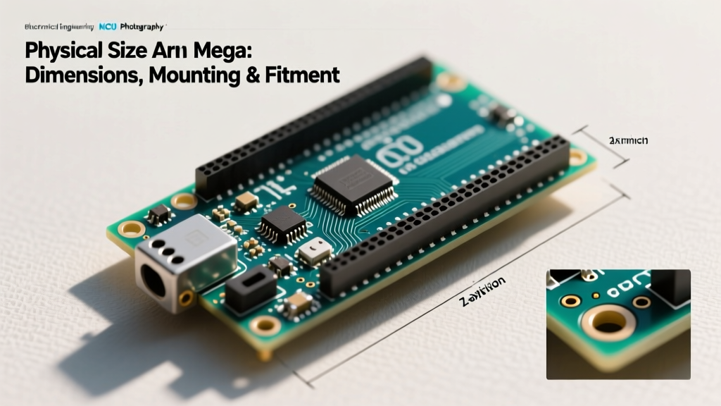
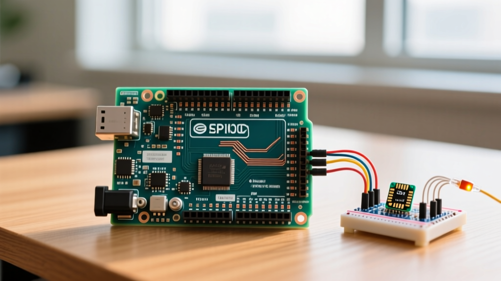
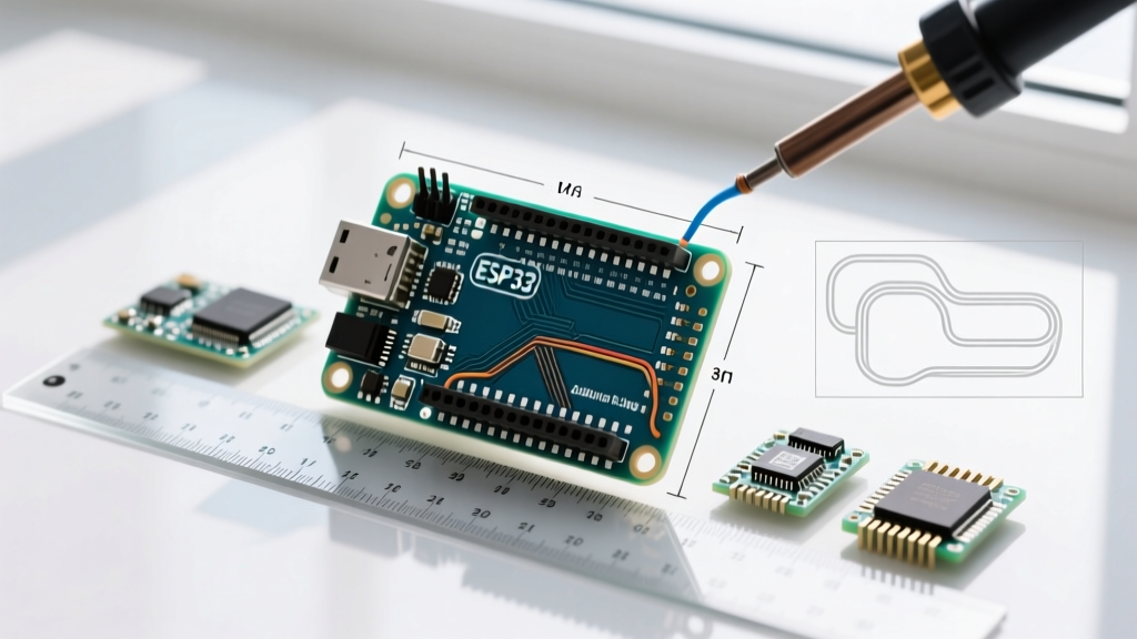
When planning a hardware migration, the physical size of Arduino Uno boards is often the most rigid engineering constraint. Whether you are prototyping on a solderless breadboard or designing a custom 3D-printed enclosure, the Uno's footprint dictates your spatial budget. The official Arduino Uno R3 and the newer R4 Minima share the same fundamental PCB dimensions: 68.58 mm x 53.34 mm (2.7 x 2.1 inches). However, the physical envelope extends beyond the bare fiberglass.
According to the official Arduino hardware documentation, the maximum width is determined by the female header pins, while the length is heavily influenced by the USB port overhang. On the classic R3, the USB-B port extends approximately 1.6 mm past the PCB edge. On the R4 Minima, the transition to a flush USB-C connector alters the mechanical clearance required in legacy enclosures.
Mounting Hole Geometry
Migrating away from the Uno requires understanding its mounting matrix. The board features four M3-compatible mounting holes (3.2 mm diameter). The spatial relationship between these holes is critical for CAD modeling:
- Top-Left to Top-Right: 48.26 mm (1.9 inches)
- Top-Left to Bottom-Left: 50.8 mm (2.0 inches)
- Bottom-Left to Bottom-Right: 48.26 mm (1.9 inches)
- Top-Right to Bottom-Right: 35.56 mm (1.4 inches) — Note the asymmetrical bottom-right hole placement to accommodate the barrel jack and USB clearance.
Expert Insight: When designing a universal backplate for migration, do not rely on a perfect rectangle for your standoff grid. The asymmetrical bottom-right hole on the Uno form factor is a frequent point of failure for junior engineers designing symmetrical acrylic laser-cut mounts.
The Breadboard Bottleneck: Why Size Drives Migration
One of the primary catalysts for migrating away from the Uno platform is its incompatibility with standard prototyping workflows. A standard 830-point solderless breadboard measures roughly 165 mm x 65 mm. Because the size of Arduino Uno is 53.34 mm wide, plugging it directly into the center power rails of a standard breadboard leaves only a single row of tie-points accessible on one side, and completely blocks the other.
As noted in SparkFun's comprehensive breadboard tutorial, optimal prototyping requires at least 5 to 10 accessible tie-points per pin for branching jumper wires. The Uno's width violates this spatial requirement, forcing developers to use shield stacking or awkward wire harnesses. This physical limitation is the exact reason engineers migrate to narrower DIP-form-factor boards like the Nano or Raspberry Pi Pico for the prototyping phase before returning to the Uno (or a custom PCB) for final deployment.
Platform Migration Matrix: Form Factor Comparisons
When the physical size of the Arduino Uno becomes a project bottleneck, selecting the correct migration target requires balancing spatial savings with I/O requirements. Below is a 2026 migration matrix comparing the Uno against common alternative platforms.
| Platform | Dimensions (mm) | Form Factor | Breadboard Friendly? | Avg. Price (2026) |
|---|---|---|---|---|
| Arduino Uno R4 Minima | 68.6 x 53.4 | Standard Shield | No | $20.00 |
| Arduino Nano (Classic) | 43.2 x 18.5 | DIP-30 | Yes (Leaves 3 rows) | $22.00 (Official) |
| Raspberry Pi Pico W | 51.0 x 21.0 | DIP-40 | Yes (Leaves 2 rows) | $6.00 |
| ESP32-DevKitC V4 | 49.5 x 28.5 | DIP-38 | Yes (Leaves 1 row) | $8.50 |
| Adafruit Feather RP2040 | 50.8 x 22.8 | Feather | No (Requires breakout) | $11.95 |
The Pin Pitch Trap
While the Nano and Pico solve the width issue, they introduce a new mechanical variable: the dual-row header pitch. The Uno utilizes a single-row inline header on both sides with a standard 0.1-inch (2.54 mm) pitch. The Pico and Nano also use 0.1-inch pitch, but their dual-row footprint means you cannot use standard Uno shields. If your project relies on stacking an Adafruit Motor Shield or a generic Ethernet W5500 shield, migrating to a smaller board will require a custom shield adapter or a complete wiring redesign.
Step-by-Step Enclosure Retrofitting for Migration
If you are migrating a mature project from an Uno to a smaller board (like the Pico or Nano) to save space inside an existing off-the-shelf enclosure (such as Hammond 1591 series or Pololu project boxes), follow this retrofitting protocol:
- Map the Z-Axis Clearance: The Uno sits 10.5 mm tall (excluding headers). When headers are soldered, the total Z-height jumps to 24 mm. Smaller boards like the Nano sit at 11.5 mm total. Verify your enclosure lid does not rely on the Uno's tall headers for physical support.
- Adapt the Standoffs: The Uno uses M3 (3 mm) mounting holes. The Raspberry Pi Pico uses M2 or requires M3 with nylon washers to prevent trace damage. If your enclosure has molded M3 brass inserts, use M3-to-M2.5 stepped standoffs or 3D-printed adapter sleds to secure the smaller board without cracking the PCB.
- Re-route the I/O Cutouts: The Uno's USB-B and DC barrel jack occupy a massive 35 mm x 15 mm footprint on the X-axis. Smaller boards utilize Micro-USB or USB-C, which are vertically offset from the Uno's cutouts. You will need to mill new access ports or use panel-mount USB extension cables (e.g., Adafruit Panel Mount USB-C cable, ~$6.50).
Edge Cases and Failure Modes in Form Factor Shifts
Migrating based purely on the size of Arduino Uno without accounting for electrical and thermal realities leads to specific field failures.
Thermal Dissipation in Downsized Enclosures
The Uno's large 53.34 mm width provides a generous copper pour area that acts as a passive heatsink for the onboard ATmega16U2 and linear voltage regulator (NCP1117). When migrating to a 21 mm wide Pico or an 18.5 mm Nano inside a sealed IP65 enclosure, the reduced PCB surface area severely limits thermal dissipation. If your circuit draws more than 400mA through the onboard 3.3V/5V regulator, the smaller board will trigger thermal shutdown. Solution: Bypass the onboard regulator and inject regulated 5V directly into the 5V pin when using downsized boards in sealed enclosures.
The Metal Enclosure Short Circuit
Because smaller boards lack the physical width of the Uno, engineers often push them to the extreme edges of metal project boxes to align USB ports with cutouts. This places the raw, unmasked edges of the PCB (where vias and ground planes are exposed) within 1 mm of the aluminum chassis. Vibration will eventually wear away the solder mask, causing a dead short. Always apply Kapton tape (polyimide) to the PCB edges or use 1 mm nylon isolation washers on all metal standoffs.
Frequently Asked Questions
Can I use Uno shields on a Nano if I use extension wires?
Yes, but it is mechanically fragile. Because the Nano is 35 mm shorter and significantly narrower than the Uno, stacking a shield requires female-to-male jumper wires. This creates a 'rat's nest' that is highly susceptible to EMI (Electromagnetic Interference) and physical disconnects. For shield compatibility, use the Arduino Nano Every or an official Nano Shield Adapter board.
Does the size of Arduino Uno R4 differ from the R3?
The PCB footprint (68.58 x 53.34 mm) and mounting holes are identical to maintain backward compatibility with decades of third-party shields and enclosures. However, the R4 Minima removes the bulky DC barrel jack and replaces the USB-B overhang with a flush USB-C port, slightly altering the mechanical clearance required on the X and Y axes of tight-fitting 3D printed cases.
What is the best platform for high-density sensor arrays?
If your project requires more than 14 digital I/O pins but you cannot accommodate the physical size of the Arduino Uno or Mega, migrate to the ESP32-S3 DevKitC-1. It offers 45 usable GPIO pins in a footprint of just 69 mm x 25 mm, providing Mega-level I/O density in a breadboard-friendly form factor. For deeper architectural insights, refer to the Raspberry Pi microcontroller documentation or Espressif's official hardware guidelines for pin-multiplexing constraints.