
The Reality of PWM pins on Arduino Uno
The classic Arduino Uno (based on the ATmega328P) has been the undisputed king of introductory electronics for over a decade. However, as modern DIY projects in 2026 demand smoother motor control, silent LED dimming, and complex multi-axis robotics, makers inevitably hit a hardware wall. Specifically, the limitations of the PWM pins on Arduino Uno boards force engineers to look toward more capable platforms like the ESP32-S3 or the Raspberry Pi Pico (RP2040).
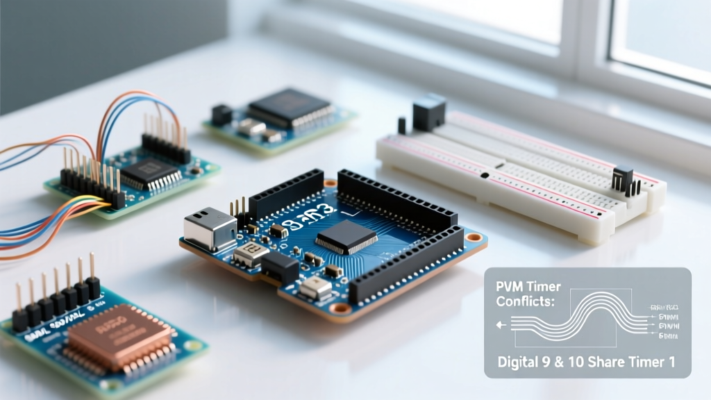
Before migrating, you must understand exactly what you are leaving behind. The Uno features six dedicated hardware PWM pins, marked with a tilde (~) on the silkscreen: 3, 5, 6, 9, 10, and 11. These are not created equal; they are tied to three distinct internal timers, each with its own quirks and default frequencies.
Timer Architecture and the 490Hz Bottleneck
- Timer0 (8-bit): Controls pins 5 and 6. Default frequency is ~976 Hz. Critical Warning: Timer0 is hardcoded to handle
millis(),delay(), andmicros(). Altering its prescaler to change PWM frequency will break all native Arduino timing functions. - Timer1 (16-bit): Controls pins 9 and 10. Default frequency is ~490 Hz. Because it is a 16-bit timer, it can be manually reconfigured for high-resolution phase-correct PWM without breaking core system functions.
- Timer2 (8-bit): Controls pins 3 and 11. Default frequency is ~490 Hz. Often used for tone generation or basic motor control.
Expert Insight: The default 490 Hz frequency on pins 3, 9, 10, and 11 is notoriously problematic for DC motor control and Class-D audio amplifiers. At 490 Hz, the PWM switching falls squarely within the human hearing range (20 Hz - 20 kHz), resulting in an audible, high-pitched coil whine. Migrating to a 32-bit platform allows you to push PWM frequencies above 20 kHz, rendering motor noise completely inaudible.
The Migration Matrix: Uno vs. Modern 32-Bit Platforms
When you outgrow the 6-channel, 8-bit resolution limit of the ATmega328P, you need a platform that offers hardware-level PWM scaling. Below is a 2026 comparison of the most common migration targets.
| Platform (MCU) | PWM Channels | Max Resolution | Max Frequency | Logic Level | 2026 Avg. Price |
|---|---|---|---|---|---|
| Arduino Uno R3 (ATmega328P) | 6 | 8-bit (256 steps) | ~62 kHz (with trade-offs) | 5.0V | $14.00 (Clone) |
| ESP32-S3-DevKitC | Up to 16 (LEDC) | 14-bit (16384 steps) | 40 MHz | 3.3V | $6.50 |
| Raspberry Pi Pico (RP2040) | 16 (8 Slices) | 16-bit (65536 steps) | 125 MHz (via PIO) | 3.3V | $4.00 |
| Teensy 4.1 (i.MX RT1062) | Up to 31 | 16-bit | ~150 MHz | 3.3V | $32.00 |
Hardware Pitfalls: The 5V to 3.3V Logic Trap
The most common failure mode when migrating away from the PWM pins on Arduino Uno is ignoring the voltage drop. The Uno outputs 5V logic on its PWM pins. The ESP32 and RP2040 output 3.3V logic. This 1.7V difference will break poorly designed power stages.
The MOSFET Gate Threshold (Vgs) Problem
Consider the ubiquitous IRF520 MOSFET driver module, sold in bulk on Amazon and AliExpress. The IRF520 is a standard-level MOSFET that requires a Gate-to-Source voltage (Vgs) of 10V to fully open its channel and achieve its rated low RDS(on).
- On the Uno (5V PWM): The IRF520 partially turns on. It will switch a 12V LED strip, but the internal resistance remains high, causing the MOSFET to overheat rapidly at currents above 2A.
- On the ESP32/Pico (3.3V PWM): 3.3V is below the typical threshold voltage to trigger the gate. The MOSFET will either fail to switch entirely or operate in a highly resistive linear region, potentially destroying the component and your 3.3V microcontroller via back-EMF or thermal runaway.
The Migration Solution: Discard standard-level MOSFETs. When migrating to 3.3V platforms, you must use Logic-Level MOSFETs like the IRLZ44N or IPB107N20N3, which are guaranteed to fully saturate at Vgs = 4.5V or lower. Alternatively, use a dedicated gate driver IC like the TC4420 to step the 3.3V PWM signal up to 12V for driving heavy industrial IGBTs or high-power standard MOSFETs.
Software Translation: Rewriting Your PWM Code
The analogWrite(pin, duty) function is deeply ingrained in the Arduino ecosystem. However, 32-bit platforms handle PWM generation via entirely different hardware peripherals.
Migrating to ESP32 (Arduino Core 3.x)
In older ESP32 cores, you had to use the verbose ledcSetup() and ledcAttachPin() functions. As of 2026, the ESP32 Arduino Core 3.x has unified the API, but understanding the underlying Espressif LEDC (LED Control) peripheral is vital for high-frequency applications.
// ESP32 Arduino Core 3.x Unified Approach
void setup() {
  // Pin 16, 20000 Hz (silent motor control), 12-bit resolution (0-4095)
  analogWriteFrequency(20000);
  analogWriteResolution(12);
  analogWrite(16, 2048); // 50% duty cycle
}
The LEDC peripheral allows you to route PWM to almost any GPIO pin, entirely eliminating the strict pin-mapping constraints of the Arduino Uno's timers.
Migrating to Raspberry Pi Pico (RP2040)
The RP2040 handles PWM via 8 hardware "slices," each controlling two GPIO pins (A and B), yielding 16 independent PWM channels. According to the official Raspberry Pi Pico documentation, if you attempt to set different frequencies on Pin 0 and Pin 1 (which share Slice 0), the hardware will force them to share the same frequency, though duty cycles can remain independent.
// RP2040 (Arduino-Pico Core) Approach
void setup() {
  // Set GPIO 2 to 25kHz for a Class-D audio amplifier
  analogWriteFreq(25000);
  analogWriteRange(1023); // 10-bit resolution
  analogWrite(2, 512);
}
Advanced Edge Case: High-Resolution LED Dimming
If your project involves architectural LED lighting or photography studio arrays, the 8-bit resolution (256 steps) of the PWM pins on Arduino Uno is insufficient. At low duty cycles (e.g., 1% to 5%), 8-bit PWM causes visible "stepping" or flickering when dimming lights.
By migrating to the RP2040's 16-bit PWM slices (65,536 steps), you achieve buttery-smooth logarithmic dimming curves that mimic professional DMX512 lighting consoles. When writing your migration code, ensure you map your perceived brightness using a CIE 1931 lightness correction algorithm rather than a simple linear map, leveraging the extra resolution to eliminate low-end flicker.
Summary: When to Make the Jump
The Arduino Uno remains a fantastic tool for learning and simple 5V logic prototyping. However, you should immediately migrate your PCB design to an ESP32 or RP2040 if your project requires:
- More than 6 PWM channels (e.g., hexacopter flight controllers or multi-zone HVAC systems).
- Frequencies above 1 kHz to eliminate audible coil whine in motors or to drive switch-mode power supplies (SMPS).
- Resolutions greater than 8-bit for precision analog emulation or smooth optical transitions.
- Native wireless telemetry alongside motor control (making the ESP32 the undisputed choice).
By understanding the hardware timers you are leaving behind and properly adapting your power-stage electronics for 3.3V logic, your platform migration will be seamless, resulting in a vastly superior end product.
For further reading on legacy timing functions, consult the Arduino analogWrite() reference documentation.