
Why the Arduino Nano is Ideal for Servo Control
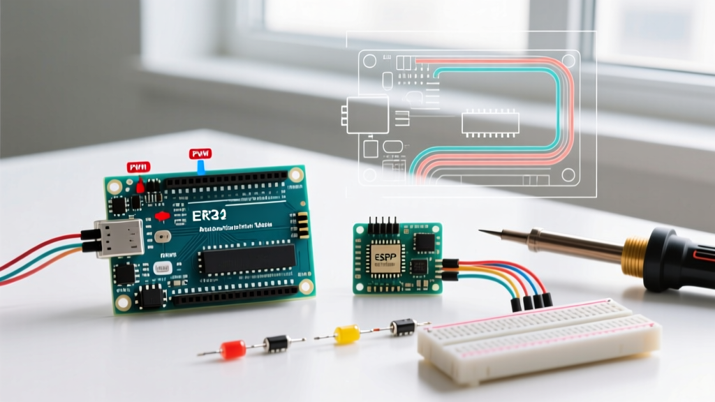
When building robotics, animatronics, or automated camera sliders, space and weight are often your biggest constraints. The Arduino Nano features the same ATmega328P microcontroller and 16 MHz clock speed as the bulky Uno, but shrinks the footprint down to just 18x45mm. This makes it the perfect brain for compact servo-driven projects. However, pairing an Arduino Nano and servo motor requires more than just plugging in three wires. Beginners frequently encounter random microcontroller resets, servo jitter, and burnt-out voltage regulators. This guide provides a deep, expert-level walkthrough on how to properly power, wire, and code your Nano for reliable servo actuation.
Understanding Your Hardware: Micro vs. Standard Servos
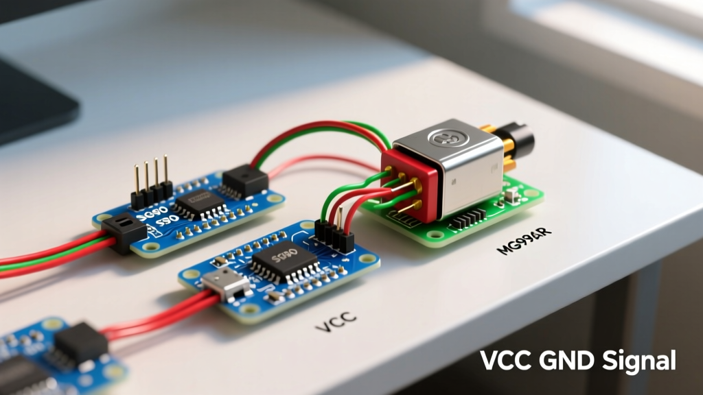
Before wiring, you must understand the electrical demands of your specific servo. The two most common servos in DIY electronics are the SG90 (micro) and the MG996R (standard metal-gear). According to the Adafruit RC Servo Guide, treating these two identically is the number one cause of project failure.
| Specification | SG90 (Micro Servo) | MG996R (Standard Servo) |
|---|---|---|
| Weight | 9 grams | 55 grams |
| Stall Torque (at 4.8V) | 1.8 kg-cm | 9.4 kg-cm |
| No-Load Current | ~10 mA | ~50 mA |
| Stall Current (Peak Draw) | ~650 mA | ~2.5 A (2500 mA) |
| Typical Cost (2026) | $2.00 - $3.50 | $7.00 - $12.00 |
While the SG90 can sometimes be powered directly from the Nano's 5V pin for very light, brief movements, the MG996R absolutely cannot. Attempting to pull 2.5 Amps through the Nano's onboard USB-to-5V linear regulator will instantly trigger a thermal shutdown or permanently destroy the voltage regulator.
The Power Trap: Why USB Power Fails
The most common failure mode when connecting an Arduino Nano and servo motor is the USB Brownout. The Nano's onboard 5V regulator (typically an AMS1117-5.0 or similar LDO on clone boards) is designed to handle a maximum continuous current of about 500mA. When a servo starts moving—especially under load or from a dead stop—it draws a massive inrush current.
Expert Rule of Thumb: Never power a standard-sized servo (like the MG996R or MG90S) directly from the Arduino Nano's 5V pin. Always use an external power supply.
The Proper Power Architecture
To achieve rock-solid stability, you must separate the logic power from the actuator power. Use a 5V or 6V UBEC (Universal Battery Eliminator Circuit) or a dedicated 4x AA battery pack to power the servo. Crucially, you must tie the ground of the external power supply to the ground of the Arduino Nano. Without a common ground, the PWM signal from the Nano will have no reference voltage, resulting in erratic servo behavior.
Step-by-Step Wiring Guide
Follow this exact pinout to ensure safe operation and proper PWM signal delivery. The Nano has specific pins marked with a tilde (~) that support hardware Pulse Width Modulation, which the Arduino Servo Library utilizes for precise timing.
- Signal Wire (Orange/White): Connect to Nano Pin D9 (a dedicated PWM pin).
- Power Wire (Red): Connect to the positive terminal of your external 5V/6V BEC or battery pack. Do not connect to the Nano 5V pin.
- Ground Wire (Brown/Black): Connect to the negative terminal of your external power supply AND to one of the Nano's GND pins. This common ground is mandatory.
- Capacitor Integration: Solder or plug a 470µF to 1000µF electrolytic capacitor (rated for at least 10V) directly across the servo's Red and Black power wires at the source. This acts as a local energy reservoir to absorb voltage spikes during motor commutation.
Precision Code: Beyond the Basic Sweep
Most beginner tutorials use the write() function, which accepts an angle from 0 to 180. However, for professional-level precision, you should use writeMicroseconds(). RC servos operate by reading a pulse width between 1000µs (0 degrees) and 2000µs (180 degrees), with 1500µs as the center. Using microseconds gives you roughly 1000 discrete steps of resolution compared to just 180 steps with the degree function.
#include <Servo.h>

Servo myServo;
const int SERVO_PIN = 9;

void setup() {
  // Attach servo and explicitly define the pulse width limits
  // This prevents the servo from over-rotating and stripping its internal gears
  myServo.attach(SERVO_PIN, 1000, 2000);
}

void loop() {
  // Move to center position (90 degrees equivalent)
  myServo.writeMicroseconds(1500);
  delay(1500);

  // Move to minimum limit (0 degrees equivalent)
  myServo.writeMicroseconds(1000);
  delay(1500);

  // Move to maximum limit (180 degrees equivalent)
  myServo.writeMicroseconds(2000);
  delay(1500);
}
Code Insight: Notice the parameters in the attach() function. By explicitly passing 1000, 2000, you override the library's default 544 to 2400 microsecond range. Many cheap servos cannot physically reach 2400µs; sending that signal will cause the motor to continuously stall against its internal mechanical hard-stop, drawing maximum current and rapidly overheating the internal DC motor.
Advanced Troubleshooting and Failure Modes
Even with correct wiring, environmental and electrical noise can cause issues. Here is how to diagnose the three most common edge cases:
1. Servo Jitter or Twitching at Rest
- Cause: Noisy power supply or missing common ground. If the servo is powered by a cheap switching buck converter, high-frequency ripple may be corrupting the PWM signal.
- Fix: Ensure the 470µF capacitor is installed. If using a long wire run (over 12 inches) for the signal wire, it acts as an antenna for EMI. Twist the signal wire around the ground wire to cancel out electromagnetic interference, or use a shielded cable.
2. Nano Randomly Resets During Movement
- Cause: Voltage brownout. Even with an external power supply, if the ground wire connecting the servo to the Nano is too thin (e.g., 28 AWG jumper wire), the high return current will create a voltage drop across the wire. This shifts the Nano's ground reference relative to its own 5V logic, triggering a brownout reset.
- Fix: Upgrade your ground wire to at least 22 AWG silicone wire. Star-ground your system where the main power ground splits off separately to the Nano and the servo, rather than daisy-chaining the ground.
3. Humming Noise and Overheating
- Cause: The servo is being commanded to a position beyond its mechanical limits, or the mechanical load is exceeding the stall torque.
- Fix: Disconnect the servo horn. Use the
writeMicroseconds()code provided above to find the true physical minimum and maximum of your specific servo. Update yourattach()parameters with these exact numbers to prevent the internal potentiometer from hitting dead zones.
By respecting the electrical boundaries of the ATmega328P and understanding the inductive nature of DC motors, your Arduino Nano and servo motor projects will transition from frustrating science experiments to reliable, deployment-ready hardware.