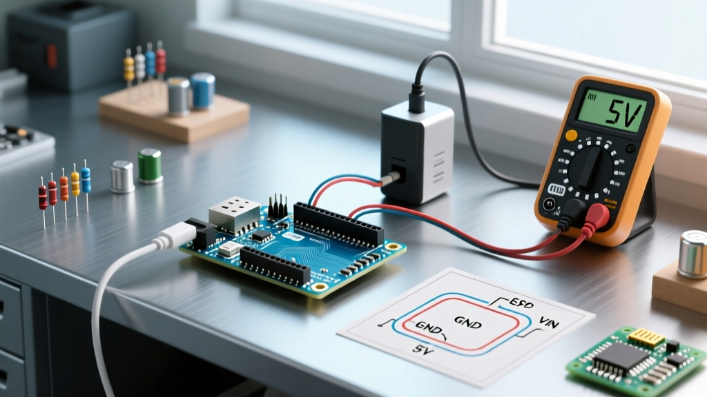

The Anatomy of Arduino Uno Input Voltage
When embarking on your first microcontroller project, understanding the Arduino Uno input voltage parameters is the difference between a successful build and a melted linear regulator. The ATmega328P (or RA4M1 on the newer R4 models) operates at 5V logic, but the board's power routing architecture dictates how you deliver that power safely. Many beginners assume that because the board accepts up to 20V on the barrel jack, operating at 15V is perfectly fine. This is a critical misconception that leads to thermal shutdown and hardware failure.
In this comprehensive setup guide, we will dissect the official voltage limits, explore the thermal realities of the on-board regulator, and walk through a safe, high-current first project setup that avoids the most common beginner power traps.
Official Limits vs. Thermal Reality
According to the official Arduino Uno R3 documentation, the board can be powered via the USB connector (5V) or the external power supply (barrel jack or Vin pin). The recommended input voltage is 7V to 12V, while the absolute limits are 6V to 20V. However, these numbers do not tell the whole story regarding current draw.
The Uno R3 utilizes an NCP1117ST50T3G linear voltage regulator to step down the barrel jack voltage to a stable 5V. Linear regulators dissipate excess voltage as heat. The formula for this thermal dissipation is:
Power Dissipated (W) = (Input Voltage - 5V) × Current Draw (A)
If you input 12V and draw 200mA (0.2A) from the 5V pin to power a few sensors and an LED, the regulator must dissipate (12 - 5) × 0.2 = 1.4 Watts. The SOT-223 package on the Uno has a thermal resistance of roughly 50°C/W. This means the regulator's temperature will rise by 70°C above ambient room temperature. If your room is 25°C, the regulator will sit at 95°C—hot enough to burn your finger and dangerously close to the chip's internal thermal shutdown threshold (usually around 125°C to 150°C).
Power Routing Comparison Matrix
| Power Method | Voltage Range | Max Safe Current (5V Pin) | Best Use Case |
|---|---|---|---|
| USB Type-B / Type-C | 5V (±5%) | ~500mA (USB 2.0 limit) | Desktop programming, low-power sensor logging |
| Barrel Jack (2.1mm) | 7V - 12V | ~200mA (at 12V) / ~500mA (at 7V) | Standalone projects with minimal 5V peripherals |
| Vin Pin | 7V - 12V | Same as Barrel Jack | Custom PCB shields, battery packs |
| 5V Pin (Direct) | 5V (Strict) | Up to 1A+ (bypasses regulator) | High-current motors, servos, LED strips |
The 9V Battery Trap: A Failure Mode Analysis
A rite of passage for many beginners is plugging a standard 9V alkaline battery into the barrel jack, only to find their project resetting randomly when a motor or servo activates. This is a fundamental misunderstanding of battery chemistry and internal resistance.
A fresh 9V alkaline battery has an internal resistance of approximately 1.5 to 2.0 ohms. When your first project commands a micro servo (like the popular SG90) to move, it can draw a stall current of up to 500mA. Using Ohm's Law (V = I × R), a 500mA draw across a 2.0-ohm internal resistance causes a 1.0V drop inside the battery itself. Add the ~0.7V drop from the Uno's reverse-polarity protection diode, and your 9V battery is suddenly delivering less than 7V to the linear regulator. The regulator loses its 'headroom' (it requires at least 1.5V above the 5V output to function), causing the 5V rail to sag to 4.2V. The ATmega328P detects this under-voltage and triggers a brown-out reset.
The 2026 Solution: Ditch the 9V alkaline. For portable setups, use a 2S LiPo battery (7.4V nominal) with a high-current buck converter, or simply use a standard 5V 2A USB wall adapter plugged directly into the USB port or the 5V pin.
Arduino Uno R3 vs. R4: Architecture Shifts
As of 2026, the Arduino Uno R4 WiFi has become a staple in the maker community. The R4 features a Renesas RA4M1 processor and a completely redesigned power architecture. Unlike the R3's linear regulator, the R4 utilizes a highly efficient switching buck converter. This means you can safely input 12V into the R4's barrel jack and draw significantly more current (up to 1A continuously) without the regulator overheating. However, the fundamental rule remains: never exceed the absolute maximum ratings, and always verify your power supply's current capacity.
First Project Setup: Powering a Servo Safely
Let's build a classic first project: a potentiometer-controlled servo motor. This project perfectly illustrates why proper Arduino Uno input voltage management is critical, as servos demand high transient current.
Hardware Requirements
- Arduino Uno R3 or R4
- SG90 Micro Servo (approx. $3)
- 10kΩ Linear Potentiometer
- 5V 2A USB Power Supply (approx. $6) & USB Cable
- Jumper wires and a breadboard
Step 1: The Hardware Wiring
We will power the logic via the USB port, but we must ensure the USB power supply can handle the servo's current spikes. A standard PC USB port limits current to 500mA, which may cause PC-side USB port resets. A dedicated 5V 2A wall adapter is mandatory.
- Potentiometer: Connect the left pin to 5V, the right pin to GND, and the middle wiper pin to Analog Pin A0.
- Servo Motor: Connect the Brown wire to GND, the Red wire to the 5V pin (or USB 5V rail), and the Orange signal wire to Digital Pin 9.
Expert Tip: If you were using multiple servos or a high-torque MG996R (which draws 2.5A at stall), you would bypass the Arduino's 5V rail entirely, using an external 5V buck converter tied to a common ground, as detailed in advanced power tutorials like those found on SparkFun's power supply guide.
Step 2: The Code
Upload the following sketch to map the analog input to the servo's PWM pulse width:
#include <Servo.h>
Servo myServo;
int potPin = A0;
int servoPin = 9;

void setup() {
  myServo.attach(servoPin);
  Serial.begin(9600);
}

void loop() {
  int potValue = analogRead(potPin);
  int angle = map(potValue, 0, 1023, 0, 180);
  myServo.write(angle);
  Serial.print("Angle: ");
  Serial.println(angle);
  delay(15);
}
Troubleshooting Brownouts and ADC Errors
Even with a proper power supply, poor wiring can mimic input voltage failures. If your Arduino resets when the servo moves, or if your analog sensors return erratic, jumping values, you are likely experiencing a ground bounce or VCC sag.
Measuring Voltage Drop with a Multimeter
Set your digital multimeter to DC Voltage. Place the black probe on the Arduino's GND pin and the red probe on the 5V pin. Watch the display while your servo sweeps. If the voltage dips below 4.7V, the ATmega328P's Brown-Out Detection (BOD) circuit will trigger. The BOD is typically set to 2.7V or 4.3V via fuse bits depending on the specific board clone or factory setting, but peripheral instability begins long before the MCU resets.
Fixing the Sag
To fix voltage sag on a breadboard, use thicker gauge wires for the power and ground rails. Standard 24 AWG jumper wires have enough resistance to cause a 0.2V drop over just a few inches when carrying 500mA. For high-current first projects, solder your power connections or use terminal blocks directly on a perfboard.
Summary & Best Practices
Mastering the Arduino Uno input voltage is about understanding the relationship between voltage, current, and heat. Remember these golden rules for every setup:
- Stick to 7V-9V if you must use the barrel jack, to keep the linear regulator cool.
- Use the 5V Pin directly (with a regulated 5V source) for high-current peripherals like motors and LED matrices.
- Avoid 9V Alkaline batteries for anything that moves, spins, or transmits via RF.
- Upgrade to a 5V 2A+ USB adapter instead of relying on your laptop's USB port for standalone testing.
By respecting the physical limits of the on-board components, you ensure your microcontroller survives the learning curve and your first project operates flawlessly.