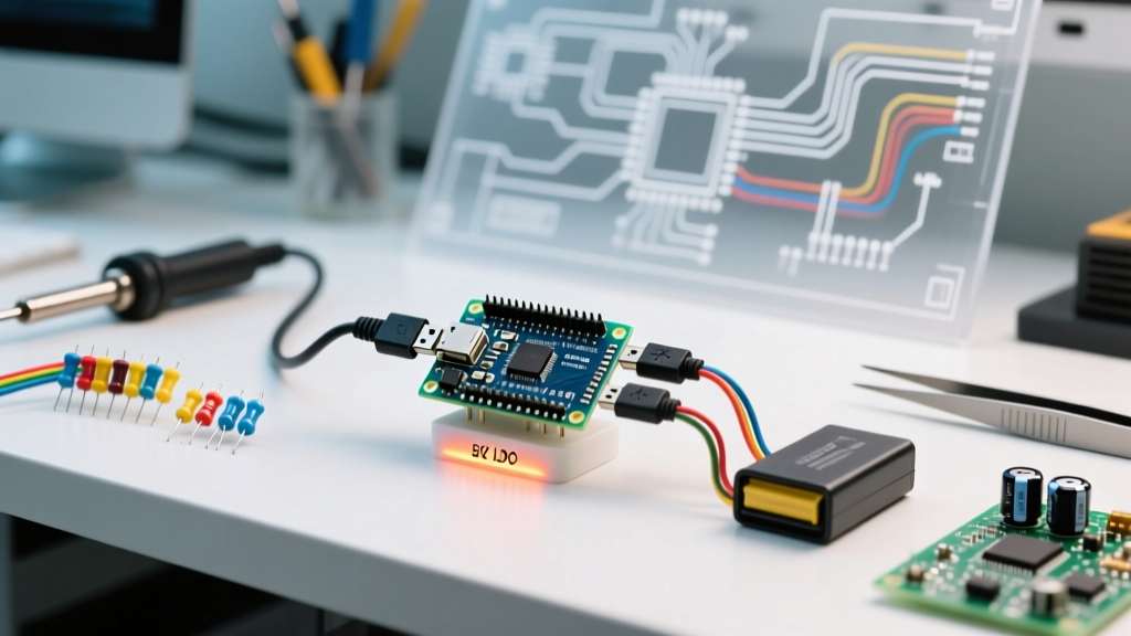

Understanding the Nano V3.0 Power Architecture
When transitioning from breadboard prototypes to standalone deployments, powering an Arduino Nano correctly is the most common stumbling block for beginners. Unlike larger boards with dedicated barrel jacks and robust heat sinks, the Nano V3.0 (and its modern clones) packs its power regulation circuitry into a tiny footprint. Misunderstanding its current limits or voltage tolerances can instantly brick the ATmega328P microcontroller or fry the onboard voltage regulator.
As of 2026, the market is flooded with both genuine Arduino Nanos (retailing around $22-$25) and ultra-cheap clone boards ($3-$5). While they share the same pinout, their underlying power components differ wildly. This guide will break down the exact electrical characteristics of the Nano's power paths, explore the thermal math behind its voltage regulator, and walk you through your first standalone, battery-powered project.
The Three Power Input Paths
According to the official Arduino Nano Documentation, the board can be powered via three distinct routes. Choosing the right one depends entirely on your project's current draw and available power source.
| Power Source | Voltage Range | Current Limit | Best Use Case |
|---|---|---|---|
| USB Mini-B | 5V DC | ~500mA (PTC Fuse) | Desktop programming, serial debugging, low-power sensor logging. |
| 5V Pin (Direct) | 4.8V - 5.2V | Depends on external source | Standalone projects powered by regulated 5V battery packs or bench supplies. |
| Vin Pin | 7V - 12V (Recommended) | Limited by LDO heat | Automotive applications, 9V battery setups, 12V lead-acid solar systems. |
Path 1: The USB Mini-B Port
The USB port provides a regulated 5V supply. A resettable PTC polyfuse (usually rated at 500mA) sits between the USB VBUS line and the board's 5V net. If your connected sensors and servos draw more than 500mA, the polyfuse will heat up, increase its resistance, and throttle the voltage, causing the Nano to brown out and reset.
Path 2: The 5V Pin (The Regulator Bypass)
Injecting exactly 5V into the '5V' pin bypasses the onboard linear regulator entirely. This is the most efficient way to power a Nano in a standalone setup, provided your external 5V source is clean and regulated. Warning: Never inject more than 5.5V into this pin, as it connects directly to the ATmega328P's VCC rail.
Path 3: The Vin Pin (Unregulated Input)
The Vin (Voltage In) pin feeds directly into the onboard Low Dropout (LDO) voltage regulator. While the absolute maximum input voltage is technically 20V, the practical limit is 12V due to severe thermal constraints, which we will calculate below.
The Hidden Bottleneck: Onboard LDO Thermal Limits
The most critical concept to master when powering an Arduino Nano via the Vin pin is thermal dissipation. The Nano uses a surface-mount SOT-223 package LDO (often an LM1117-5.0 or a generic equivalent). This component steps down your input voltage to 5V, but it does so by burning the excess voltage as heat.
The power dissipated as heat ($P_d$) is calculated using the formula:
$P_d = (V_{in} - 5V) \times I_{load}$
The SOT-223 package has a thermal resistance ($\theta_{JA}$) of roughly 50°C/W. This means for every watt of heat generated, the internal junction temperature rises 50°C above ambient room temperature (usually 25°C). The regulator's internal thermal shutdown triggers at approximately 150°C.
Real-World Thermal Scenarios
- Scenario A (9V Battery, 50mA draw): $P_d = (9 - 5) \times 0.05 = 0.2W$. Temp rise = 10°C. Result: Perfectly safe.
- Scenario B (12V Supply, 150mA draw): $P_d = (12 - 5) \times 0.15 = 1.05W$. Temp rise = 52.5°C. Regulator hits 77.5°C. Result: Hot to the touch, but safe for continuous operation.
- Scenario C (12V Supply, 300mA draw): $P_d = (12 - 5) \times 0.3 = 2.1W$. Temp rise = 105°C. Regulator hits 130°C. Result: Dangerously close to thermal shutdown; the board will randomly reboot.
For deep technical specifications on these thermal limits, refer to the Texas Instruments LM1117 Datasheet. If your project requires more than 200mA at 12V, you must abandon the Nano's onboard regulator and use an external switching buck converter (like an LM2596 module) to step the voltage down to 5V before feeding it into the Nano's 5V pin.
Critical Failure Modes to Avoid
When learning about Arduino power supplies, avoiding catastrophic mistakes is just as important as knowing the right way to wire things. Avoid these three common edge cases:
- The 5V Backfeed Trap: If you connect a 5V battery to the 5V pin and plug in the USB cable simultaneously, the two 5V sources will fight each other. Current will flow backward through the USB port, potentially frying your computer's USB hub or the Nano's USB-to-Serial IC.
- The 12V Lead-Acid Spike: A '12V' car or solar battery actually peaks at 14.4V when charging. Feeding 14.4V into the Vin pin of a cheap clone Nano will often cause the LDO to fail short, sending 14.4V directly into the 5V logic rail and instantly killing the ATmega328P.
- The 9V Alkaline Voltage Sag: Standard 9V alkaline batteries drop below 7V very quickly under load. If the voltage drops below the LDO's dropout threshold (usually ~1.2V above the 5V output), your Nano will brown out and reset, even if the battery still has 'juice' left.
Genuine vs. Clone Nano: Power Component Differences
Not all Nanos are created equal. Genuine boards use high-quality FT232RL USB-to-Serial chips and robust, well-sourced LDOs. The vast majority of 2026 market clones use the CH340G USB chip and the cheapest available SOT-223 regulators. These clone regulators often lack proper internal thermal protection and have higher voltage dropout. When designing a mission-critical project, always budget for a genuine board or a premium clone from a reputable vendor, and test the LDO temperature with a thermal camera or thermocouple under maximum load.
Tutorial: Your First Standalone 9V Nano Project
Let's move away from the USB cable and build a standalone deployment. We will create an autonomous temperature-alert beacon powered by a 9V battery via the Vin pin.
Bill of Materials (BOM)
- 1x Arduino Nano V3.0 (with headers soldered)
- 1x 9V Alkaline Battery
- 1x 9V Battery Snap Connector with bare leads
- 1x 5mm Red LED
- 1x 220Ω Through-hole Resistor
- 1x Mini Breadboard
Step 1: Wiring the Circuit
Power Connections: Take your 9V snap connector. Connect the Red wire (+9V) to the Vin pin on the Nano. Connect the Black wire (GND) to any of the three GND pins on the Nano.
Output Connections: Insert the 220Ω resistor into the breadboard. Connect one end to the Nano's D13 pin. Connect the other end to the Anode (long leg) of the LED. Connect the Cathode (short leg) of the LED to the breadboard's ground rail, and jump this ground rail to the Nano's GND pin.
Step 2: Upload the Code
Plug the Nano into your PC via USB. Open the Arduino IDE and upload the standard 'Blink' example (File > Examples > 01.Basics > Blink). Once the upload is complete and the onboard pin 13 LED is flashing, unplug the USB cable.
Step 3: Standalone Deployment
Snap the 9V battery onto the connector. The Nano will instantly boot, and your external LED will begin blinking, completely independent of your computer. Touch the small metal tab of the LDO regulator (located near the USB port) after 5 minutes. It should be warm, but not burning hot, confirming our thermal math from earlier holds true for this low-current (~30mA) circuit.
Summary
Mastering the art of powering an Arduino Nano requires respecting the physical limits of its linear voltage regulator. By understanding the difference between the 5V rail and the Vin rail, calculating your thermal budget, and avoiding backfeed scenarios, you can reliably deploy Nano-based projects in the field for months on end. Always prioritize external switching regulators for high-current, high-voltage applications to keep your microcontroller safe and stable.