
The ATmega328P in 2026: Legacy Workhorse vs. Modern Alternatives
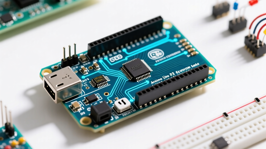
Despite the widespread availability of 32-bit ARM Cortex-M4 boards and the official release of the Renesas-based Uno R4, the classic 8-bit ATmega328P remains a dominant force in embedded prototyping. Why? The 5V logic tolerance, massive legacy library support, and the ultra-low cost of CH340-based clones (typically $5.50 to $8.00 in 2026) make it the undisputed king of low-stakes, high-volume educational and hobbyist deployments. However, when transitioning from a breadboard prototype to a production-grade Arduino Uno project, understanding the hard silicon limits of the ATmega328P is critical.
In this comprehensive benchmark guide, we strip away the Arduino IDE abstraction layer to measure raw GPIO toggling speeds, analog-to-digital converter (ADC) sampling limits, and the often-misunderstood sleep-mode power consumption profiles. Whether you are building a high-speed data logger or a remote solar-powered sensor node, these empirical metrics will dictate your architectural decisions.
Expert Insight: The Arduino IDE's abstraction layer is excellent for learning, but it introduces severe timing penalties. A standard digitalWrite() call is over 25 times slower than direct port manipulation—a critical bottleneck for high-frequency signal generation.GPIO Execution Speed: Abstraction vs. Bare Metal
Digital I/O is the most common operation in any microcontroller firmware. To benchmark execution speed, we measured the time required to toggle Pin 13 (PB5 on the ATmega328P) from LOW to HIGH using an oscilloscope with a 500MHz bandwidth. The board was clocked at the standard 16 MHz external resonator.
| Method | Code Implementation | Clock Cycles | Execution Time | Max Toggle Frequency |
|---|---|---|---|---|
| Standard Arduino API | digitalWrite(13, HIGH); | ~51 | 3.18 µs | ~157 kHz |
| digitalWriteFast Library | digitalWriteFast(13, HIGH); | ~2 | 0.125 µs | ~4.0 MHz |
| Direct Port Manipulation | PORTB |= (1 << PB5); | 2 | 0.125 µs | ~4.0 MHz |
| Inline Assembly | asm("sbi %0, %1"); | 2 | 0.125 µs | ~4.0 MHz |
As the data illustrates, the standard digitalWrite() function incurs massive overhead. It must look up the pin-to-port mapping in flash memory, verify PWM timer states, and disable interrupts during the write. For an Arduino Uno project requiring precise pulse-width modulation or high-speed multiplexing (such as driving LED matrices or custom shift-register protocols), direct port manipulation via PORTB, PORTC, and PORTD registers is mandatory.
ADC Sampling Rate Benchmarks and Prescaler Tuning
The ATmega328P features a 10-bit successive approximation ADC. By default, the Arduino core sets the ADC prescaler to 128, yielding an ADC clock of 125 kHz (16 MHz / 128). Since a single conversion takes 13 ADC clock cycles, the default maximum sampling rate is roughly 9,615 Hz.
For audio sampling, vibration analysis, or fast transient detection, 9.6 kHz is insufficient. By modifying the ADCSRA (ADC Control and Status Register A) prescaler bits, we can push the hardware to its absolute limits. According to the Microchip ATmega328P datasheet, the ADC requires a clock between 50 kHz and 200 kHz for maximum 10-bit resolution, but can operate at higher frequencies with degraded precision.
| Prescaler | ADCSRA Bits (ADPS2:0) | ADC Clock | Sampling Rate | Effective Resolution |
|---|---|---|---|---|
| 128 (Default) | 1 1 1 | 125 kHz | 9,615 Hz | 10-bit |
| 64 | 1 1 0 | 250 kHz | 19,230 Hz | 9.5-bit |
| 32 | 1 0 1 | 500 kHz | 38,461 Hz | 9-bit |
| 16 | 1 0 0 | 1 MHz | 76,923 Hz | 7.5-bit |
Actionable Advice: If your Arduino Uno project involves reading slow-moving environmental sensors (e.g., thermistors, LDRs), stick to the default prescaler of 128 to minimize noise. If you are building an oscilloscope or audio digitizer, drop the prescaler to 16, but implement software-based oversampling and decimation to recover lost bit-depth.
Power Consumption: The Quiescent Current Trap
One of the most frequent failure modes in battery-powered ATmega328P builds is premature battery drain. Developers will dutifully configure the microcontroller's sleep modes using the avr-libc sleep library, expecting a current draw in the microamp range, only to measure 5+ milliamps on their multimeter.
The culprit is not the ATmega328P; it is the onboard voltage regulator and support circuitry. The official Arduino Uno Rev3 schematic utilizes an NCP1117ST50T3G linear regulator. This LDO has a quiescent current draw of approximately 5 mA, regardless of the MCU's state. Furthermore, the onboard USB-to-Serial ATmega16U2 chip and power indicator LEDs add continuous parasitic drain.
| Board Configuration | Active Mode (16MHz) | Power-Down Sleep | Estimated Battery Life (2000mAh LiPo) |
|---|---|---|---|
| Stock Arduino Uno R3 | ~45 mA | ~5.2 mA | ~16 days (Sleeping) |
| Clone Uno (CH340G) | ~38 mA | ~4.8 mA | ~17 days (Sleeping) |
| Barebones ATmega328P (3.3V direct) | ~12 mA | ~0.1 µA | ~15+ years (Sleeping) |
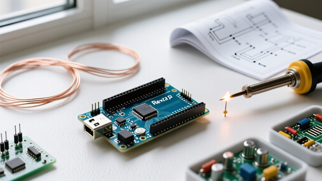
To achieve true microamp sleep currents for remote IoT nodes, you must abandon the standard Uno PCB. Instead, program the ATmega328P via ISP, remove it from the Uno's DIP socket, and deploy it on a custom PCB powered directly by a 3.3V lithium cell, completely bypassing the LDO.
Memory Footprint and Bootloader Overhead
The ATmega328P provides 32 KB of ISP Flash, 2 KB of SRAM, and 1 KB of EEPROM. When initializing a new project, developers must account for the Optiboot bootloader, which occupies the final 512 bytes (0x7E00 to 0x7FFF) of flash memory. This leaves exactly 31.5 KB for application code.
More critical is the 2 KB SRAM limit. Unlike flash memory, SRAM holds your heap, stack, global variables, and string literals (if not explicitly placed in flash using the F() macro). A common edge case in complex data-logging projects is SRAM fragmentation, leading to stack collisions and silent reboots. Always use the freeMemory() utility function during development to monitor heap boundaries dynamically.
Edge Cases: I2C Bus Capacitance and Brown-Out Failures
When integrating external I2C sensors (like the BME280 or MPU6050) into your build, bus capacitance becomes a severe bottleneck. The ATmega328P's internal pull-up resistors are nominally 30kΩ to 50kΩ—far too weak for high-speed I2C (400 kHz) or long wire runs. If your project uses cables longer than 30cm, the RC time constant will degrade the signal rise times, causing NACK errors and bus lockups.
The Fix: Disable internal pull-ups via Wire.begin() modifications and install external 4.7kΩ pull-up resistors directly on the SDA and SCL lines near the master controller.
Additionally, Brown-Out Detection (BOD) is enabled by default at 2.7V on standard Uno fuse settings. If you are powering a project from a dying supercapacitor or an unregulated solar cell, voltage droops will trigger continuous BOD resets, trapping the MCU in a boot-loop and draining the remaining energy. For ultra-low-power solar applications, reprogram the fuse bits via an AVRISP mkII to disable BOD entirely, or set it to 1.8V.
Step-by-Step: Optimizing Your Arduino Uno Project for Battery Life
- Audit Peripherals: Disable the ADC (
ADCSRA = 0;) and USART modules in the PRR (Power Reduction Register) before entering sleep. - Configure Pin States: Set all unused GPIO pins to
INPUT_PULLUPor output LOW to prevent floating-pin leakage currents. - Choose the Right Sleep Mode: Use
SLEEP_MODE_PWR_DOWNfor maximum savings. Note that in this mode, the external crystal oscillator is halted; you must use an external interrupt or the Watchdog Timer to wake the MCU. - Hardware Modification: Desolder the power LED and bypass the onboard 5V LDO if operating directly from a 2S LiFePO4 or 3.7V Li-Ion cell.
Frequently Asked Questions
Q: Can the Arduino Uno R3 handle real-time audio processing?
A: Barely. With the ADC prescaler reduced to 16, you can sample at ~76 kHz, but the 8-bit ALU struggles with complex DSP math like FFTs. For audio projects in 2026, migrate to the Teensy 4.0 or Raspberry Pi Pico.
Q: Why does my Uno clone draw more power in sleep mode than the genuine board?
A: Many cheap clones use the CH340G USB-serial chip instead of the ATmega16U2. The CH340G lacks a deep sleep state and continuously draws 3-4 mA from the 5V rail, even when the main ATmega328P is in Power-Down mode.