
The Enduring Legacy of the ESP8266 in Modern IoT
Despite the widespread adoption of the dual-core ESP32 and the newer ESP32-C3, the original ESP8266 remains a cornerstone of the DIY electronics and commercial IoT landscape in 2026. Its single-core 80MHz (overclockable to 160MHz) Tensilica L106 processor, combined with a mature Wi-Fi stack and ultra-low pricing, makes it the undisputed champion for simple, cost-effective wireless sensor nodes. When developing for this chip, the ESP8266 Arduino Core provides a robust, familiar C++ environment that abstracts away the complexities of the native Espressif NONOS or RTOS SDKs.
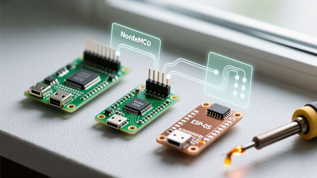
However, the raw ESP8266EX chip requires external SPI flash, a 3.3V voltage regulator, and a USB-to-UART bridge for programming. This has led to a fragmented market of development boards. In this comprehensive review, we dissect the three most popular ESP8266 development boards—the NodeMCU V3, the Wemos D1 Mini, and the barebones ESP-01S—evaluating their hardware quirks, power consumption realities, and suitability for different project architectures.
Board-by-Board Hardware Review
1. NodeMCU V3 (LoLin Variant): The Prototyping Workhorse
The NodeMCU V3, specifically the LoLin-manufactured variant, is the most ubiquitous ESP8266 board on the market. It features a wide form factor that unfortunately spans both sides of a standard breadboard, leaving no room for jumper wires unless you use a dual-breadboard setup.
- USB-UART Bridge: CH340G. While cheap, the CH340G requires manual driver installation on Windows 11 and macOS, and is notorious for causing kernel panics on older macOS versions if unofficial drivers are used.
- Voltage Regulation: Equipped with an AMS1117-3.3 LDO. This is a critical failure point for battery-operated projects. The AMS1117 has a high quiescent current (~5mA) and a high dropout voltage. If you attempt to power the board via the VIN pin with a 3.7V LiPo battery, the LDO will fail to regulate, resulting in unstable brownouts.
- Deep Sleep Reality: While the ESP8266 chip itself draws roughly 20µA in deep sleep, the NodeMCU V3's onboard power LED and the AMS1117 LDO will push the total board idle current to ~8mA. To achieve true low-power deep sleep, you must physically desolder the power LED and bypass the LDO by feeding 3.3V directly into the 3.3V pin.
- Price Range: $3.50 - $5.00 USD.
2. Wemos D1 Mini (V4.0.0): The Space-Constrained Champion
The Wemos D1 Mini solved the NodeMCU's breadboard problem with a compact 25.4mm x 34.2mm footprint. The latest V4.0.0 revisions have modernized the board significantly, making it the premier choice for enclosed, space-constrained IoT devices.
- USB Interface: Upgraded to USB-C, utilizing the CH340K or CP2104 depending on the specific manufacturing batch. The USB-C connector is a massive reliability upgrade over the fragile Micro-USB ports found on V3 boards.
- Flash Memory: Standardized at 4MB (32Mbit). This is crucial for Over-The-Air (OTA) updates, as 4MB allows for two ~1.8MB sketch partitions, ensuring safe rollbacks if a firmware flash fails.
- Ecosystem: The D1 Mini's true strength is its stackable shield ecosystem. You can seamlessly add relay boards, OLED displays, or battery management shields without soldering a single wire.
- Price Range: $2.80 - $4.00 USD.
3. ESP-01S: The Barebones Sensor Node
The ESP-01S is not a development board; it is a raw module with a 2x4 header. It exposes only GPIO0 and GPIO2 (plus TX/RX), making it strictly suited for single-purpose sensor nodes where size and cost are the primary drivers.
Expert Warning: The ESP-01S typically ships with 1MB (8Mbit) of SPI flash. When using the Arduino IDE for OTA updates, a 1MB flash limits your maximum sketch size to roughly 450KB. If your compiled binary exceeds this, the OTA process will corrupt the filesystem and brick the device until re-flashed via serial.
Programming the ESP-01S requires a dedicated USB-to-Serial adapter with a 3.3V logic level. Furthermore, you must manually pull GPIO0 to GND during boot to enter flash mode, and pull it HIGH (via a 10kΩ resistor) for normal execution. According to the Espressif Hardware Design Guidelines, failing to properly tie the strapping pins (GPIO0, GPIO2, GPIO15) to their correct logic states will result in boot loops or failure to execute code.
- Price Range: $1.50 - $2.20 USD.
Hardware Comparison Matrix
| Feature | NodeMCU V3 (LoLin) | Wemos D1 Mini V4 | ESP-01S (Raw Module) |
|---|---|---|---|
| USB Connector | Micro-USB | USB-C | None (Requires Adapter) |
| USB-UART IC | CH340G | CH340K / CP2104 | N/A |
| Flash Size | 4MB (32Mbit) | 4MB (32Mbit) | 1MB (8Mbit) typical |
| 3.3V LDO | AMS1117 (High Quiescent) | ME6211 (Low Quiescent) | None (External Required) |
| Deep Sleep Current | ~8mA (Stock) / 20µA (Modded) | ~3mA (Stock) / 20µA (Modded) | ~20µA (Native) |
| Breadboard Friendly | No (Too Wide) | Yes | No (Requires Breakout) |
| Avg. Cost (2026) | $4.20 | $3.40 | $1.80 |
Critical Failure Modes & Edge Cases
When running the ESP8266 at Arduino IDE environments, hardware-software mismatches often manifest in cryptic serial monitor outputs. Here are the most common edge cases and how to resolve them:
The 'rst cause:2, boot mode:(3,6)' Watchdog Reset
If your serial monitor spams rst cause:2, boot mode:(3,6), your code is triggering the hardware Watchdog Timer (WDT). The ESP8266 Arduino Core uses a software watchdog that resets the chip if the loop() function blocks for more than 3.2 seconds without yielding to the background Wi-Fi stack. Fix: Insert yield(); or delay(1); inside long-running while loops, or use ESP.wdtDisable() cautiously if you are writing bare-metal timing code.
Wi-Fi TX Brownouts
When the ESP8266 transmits a Wi-Fi packet, current draw spikes to 300mA - 400mA for a few milliseconds. If you are powering an ESP-01S or a NodeMCU via a weak 3.3V USB hub or an undersized LDO, the voltage will dip below 2.8V, causing an immediate hardware reset. Fix: Always place a 100µF to 470µF low-ESR ceramic or tantalum capacitor as close to the VCC and GND pins of the ESP8266 as physically possible to buffer these transient spikes.
Flash Memory Corruption via SPIFFS/LittleFS
Writing to the onboard flash memory too frequently will wear out the SPI flash sectors. The ESP8266 Arduino Core defaults to LittleFS, which includes wear-leveling, but logging data every second will still destroy a cheap 4MB flash chip within months. Fix: Buffer your sensor data in RAM and write to LittleFS in batches, or limit flash writes to configuration changes only. For high-frequency logging, use an external I2C EEPROM or push the data directly to an MQTT broker.
Setting Up the Arduino IDE (2026 Workflow)
To ensure stability and access to the latest bug fixes for the ESP8266 at Arduino IDE, avoid outdated third-party board packages. Follow this exact workflow:
- Open the Arduino IDE and navigate to File > Preferences.
- In the 'Additional boards manager URLs' field, paste the official stable JSON link:
http://arduino.esp8266.com/stable/package_esp8266com_index.json - Open the Boards Manager, search for 'esp8266', and install the latest 3.x.x core (authored by ESP8266 Community).
- Under Tools > Board, select 'LOLIN(WEMOS) D1 R2 & mini' for the D1 Mini, or 'NodeMCU 1.0 (ESP-12E Module)' for the NodeMCU.
- Set the Upload Speed to 921600 for faster flashing, and ensure Erase Flash is set to 'All Flash Contents' if you are experiencing persistent filesystem or Wi-Fi credential ghosting issues.
Final Verdict: Which Board Should You Choose?
For rapid prototyping and learning, the Wemos D1 Mini V4 is the superior choice. Its USB-C connector, breadboard-friendly footprint, and low-quiescent ME6211 LDO make it vastly superior to the aging NodeMCU V3 design. For deploying permanent, battery-powered sensor nodes in enclosed 3D-printed cases, the ESP-01S is unmatched in cost and size, provided you design a custom PCB with a dedicated 3.3V buck converter and respect the 1MB flash limitations. Avoid the NodeMCU V3 for new battery-operated designs unless you are willing to modify the hardware with a soldering iron to remove the parasitic power drains.
For further reading on optimizing Wi-Fi antenna placement and PCB trace routing for these modules, consult the official Wemos documentation and Espressif's RF design guides.