
When your project outgrows the standard 14 digital pins of an Uno, it is time to step up to the heavyweight champion of the classic lineup: the Arduino Mega 2560. Whether you are building a 3D printer controller, a complex home automation hub, or a multi-sensor environmental station, the Mega provides the I/O density and memory required for demanding tasks. This beginner guide cuts through the fluff and gives you the exact hardware specifications, power limitations, and wiring realities you need to succeed in 2026.
Why Choose the Arduino Mega 2560 Over the Uno?
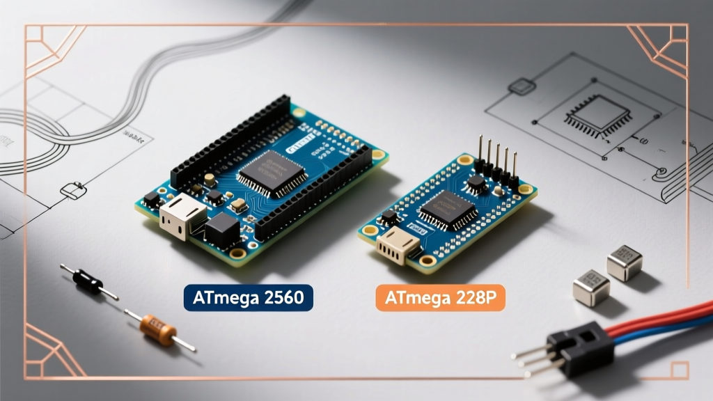
The most common question beginners ask is whether the extra cost and physical footprint of the Mega are justified. The answer depends entirely on your memory and pinout requirements. The Mega 2560 Rev3 is built around the ATmega2560 microcontroller, offering a massive upgrade in almost every metric.
| Specification | Arduino Uno R3 / R4 | Arduino Mega 2560 Rev3 |
|---|---|---|
| Microcontroller | ATmega328P / RA4M1 | ATmega2560 |
| Flash Memory | 32 KB / 256 KB | 256 KB (8 KB used by bootloader) |
| SRAM | 2 KB / 32 KB | 8 KB |
| Digital I/O Pins | 14 | 54 (15 provide PWM output) |
| Analog Input Pins | 6 | 16 |
| Hardware Serial (UART) | 1 | 4 (Serial, Serial1, Serial2, Serial3) |
| Typical Genuine Price | $27.00 - $35.00 | $45.00 - $52.00 |
The four hardware UARTs are a game-changer for beginners. On an Uno, uploading code via USB occupies the single serial port, meaning you cannot easily debug while communicating with a GPS module or a Bluetooth HC-05. The Mega allows you to dedicate Serial to the USB monitor, Serial1 to a GPS, Serial2 to an RS485 bus, and Serial3 to a cellular modem simultaneously without relying on slow software serial libraries.
Anatomy of the Mega 2560: Pinout Realities
According to the official Arduino hardware documentation, the board features 54 digital I/O pins. However, not all pins are created equal. Understanding the specific pin groups is critical to avoiding hardware conflicts.
PWM and Interrupt Pins
Out of the 54 digital pins, 15 support hardware Pulse Width Modulation (PWM). These are pins 2 through 13, plus pins 44, 45, and 46. If you are driving multiple servos or dimming high-power LED arrays, you must map your outputs to these specific pins using the analogWrite() function.
For external hardware interrupts (using attachInterrupt()), the Mega supports interrupts on pins 2, 3, 18, 19, 20, and 21. Note that pins 20 and 21 are shared with the I2C bus (SDA and SCL). If you are using an I2C OLED display or BME280 sensor, you lose two interrupt-capable pins.
The SPI and ICSP Headers
Unlike the Uno, where the SPI pins (MOSI, MISO, SCK) are neatly mapped to digital pins 11, 12, and 13, the Mega 2560 routes hardware SPI to pins 50 (MISO), 51 (MOSI), and 52 (SCK). Pin 53 serves as the Slave Select (SS). If you are porting an Uno shield that relies on SPI, ensure it utilizes the 6-pin ICSP header in the center of the board, which maintains SPI compatibility across both form factors.
Powering the Board: Thermal Limits and Failure Modes
The most frequent way beginners destroy their first Mega is by misunderstanding its power delivery system. The board features three primary power input methods, each with strict limitations.
- USB Type-B (5V): The USB port is protected by a 500mA resettable polyfuse. You can safely draw up to 400mA from the 5V pin to power external sensors, provided your computer's USB port can supply the current.
- Barrel Jack (7V - 12V): The 2.1mm center-positive barrel jack feeds into an onboard NCP1117-5.0 linear voltage regulator. This is a massive thermal bottleneck.
- 5V Pin Direct Injection: Bypassing the regulator entirely by feeding a clean, regulated 5V directly into the 5V pin. This is the safest method for high-current projects but offers zero reverse-polarity or overvoltage protection.
The Linear Regulator Thermal Trap
If you plug a 12V power supply into the barrel jack and draw 300mA from the 5V pin to power a relay module, the linear regulator must dissipate the excess voltage as heat. The math is simple: (12V - 5V) * 0.3A = 2.1 Watts. The TO-220 package on the Mega cannot dissipate 2.1W without a heatsink. The regulator will hit its thermal shutdown threshold (around 150°C junction temperature) within seconds, causing the board to brownout and reset continuously.
Expert Rule of Thumb: If your external 5V load exceeds 150mA, do not use the barrel jack with a 12V supply. Either drop your input voltage to 7.5V, or power the 5V rail directly from an external buck converter (like an LM2596 module) wired straight to the 5V and GND pins.
The 5V vs 3.3V Logic Level Trap
The Arduino Mega 2560 operates at 5V logic. In 2026, the vast majority of modern sensors, displays, and communication modules (like the ESP32, BME680, and SD card breakout boards) operate strictly at 3.3V. Connecting a 5V Mega output directly to a 3.3V input pin will permanently fry the sensor's silicon.
To safely interface the Mega with 3.3V peripherals, you must use logic level shifters. For unidirectional signals (like driving a Neopixel strip or an SPI display clock), a simple voltage divider using a 1kΩ and 2kΩ resistor network works perfectly. For bidirectional I2C buses, you must use a dedicated MOSFET-based bi-directional logic level converter (such as the BSS138 breakout boards) to prevent data corruption and bus lockups.
Beginner Project: Wiring a 16-Channel Relay Module
A classic Mega project is controlling a 16-channel relay board for home automation or irrigation. Here is the exact wiring protocol to ensure reliability and prevent microcontroller damage.
- Do Not Power from the Mega: A 16-channel relay board can draw over 1.2A when all coils are energized. The Mega's 5V pin cannot handle this. Use a separate 5V 3A switching power supply.
- Optocoupler Isolation: Ensure your relay module has optocouplers. Connect the relay board's VCC to the external 5V supply, and the JD-VCC jumper to the external 5V. Connect the Mega's GND to the relay board's GND, but keep the power rails isolated.
- Active LOW Logic: Most 5V relay modules are 'Active LOW'. This means writing
digitalWrite(pin, LOW)energizes the coil. In yoursetup()function, initialize all relay pins asOUTPUTand immediately write themHIGHto ensure all relays start in the OFF state, preventing dangerous startup surges.
Buying Guide: Genuine vs. Clones in 2026
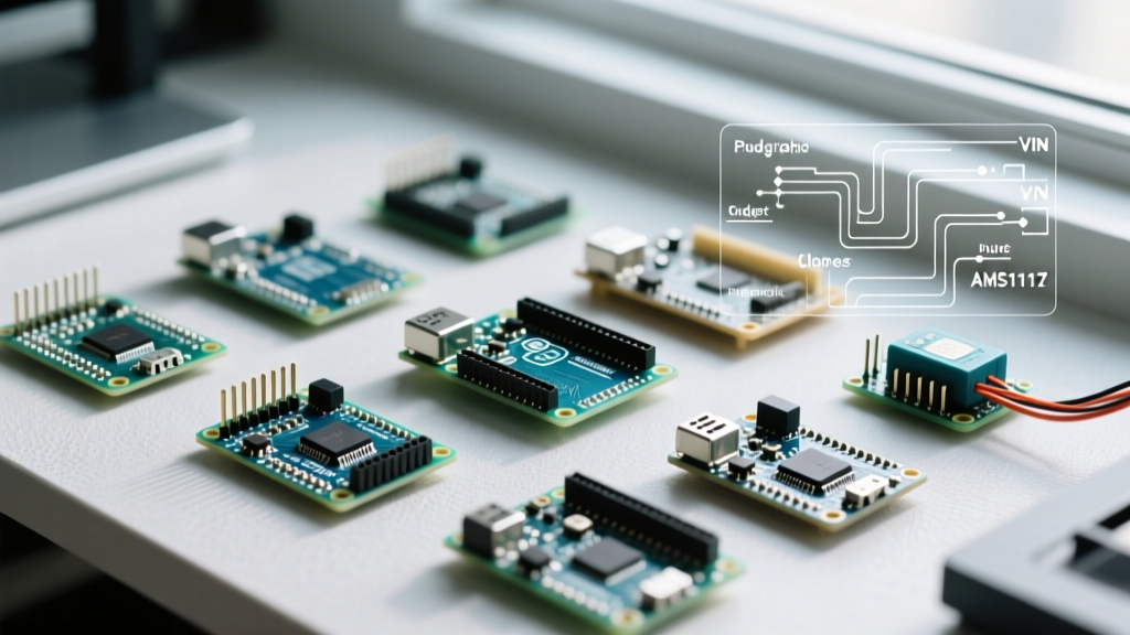
When browsing online retailers, you will notice a stark price difference. A genuine Arduino Mega 2560 Rev3 manufactured in Italy costs between $45.00 and $52.00. Third-party clones from brands like Elegoo, HiLetgo, or generic unbranded boards sell for $15.00 to $22.00.
Clones are functionally identical for 95% of beginner projects, but they cut costs in two specific areas:
- USB-to-Serial Chip: Genuine boards use the ATmega16U2. Clones almost universally use the WCH CH340G or CH340C chip. While the CH340 is reliable, it requires you to download and install specific CH340 drivers on Windows and macOS before the IDE will recognize the COM port.
- Voltage Regulator Quality: Clones often use cheaper, off-brand linear regulators that have even lower thermal thresholds than the genuine NCP1117. If you are pushing the power limits, stick to genuine hardware or use external buck converters.
For a complete overview of setting up your IDE and selecting the correct board parameters, refer to the official Arduino Mega getting started guide. By respecting the hardware limits and planning your pinout architecture early, the Mega 2560 will serve as the reliable backbone for your most ambitious DIY electronics projects.